Module 3
1. Module 3
1.45. Page 5
Module 3—Electrical Phenomena

© Nagy Melinda/shutterstock
Pulling it All Together: Charges, Fields, and Projectile Motion
As a soccer ball arcs through the air from one end of the field to the other, its path follows the characteristic pattern of a projectile, a parabolic trajectory. In the previous lab activity you used a computer simulation to discover that a charged particle can also move through a parabolic trajectory. The analysis of the data from the simulation revealed that the same equations that you used to analyze projectile motion in previous courses can be applied to a charged particle moving through a uniform electric field.
Now it’s time to apply these analytical skills to problem solving. In the next activity you will have an opportunity to apply what you learned to a variety of new situations.
Sketching the Paths of Charged Particles in Uniform Electric Fields
In the previous lab activity you developed some general statements that described how charged particles would move in specific circumstances. In this activity you will have a chance to apply those statements as you predict the motion of individual particles moving through electric fields.
Purpose
In this activity you will sketch the paths of charged particles in a number of different circumstances.
Procedure
Answer the following Assignment question.
 Module 3: Lesson 6 Assignment
Remember to submit the answer to A 1 to your teacher as part of your Module 3: Lesson 6 Assignment.
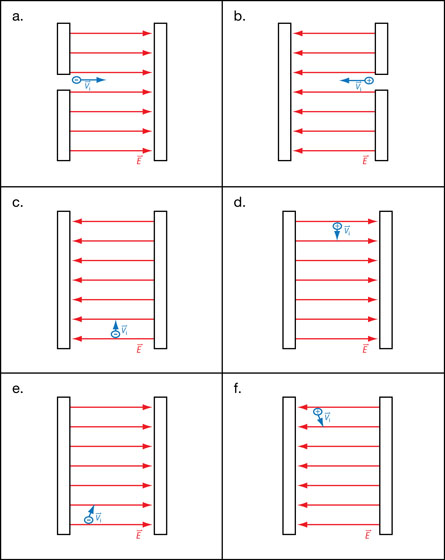
A 1. In your Module 3: Lesson 6 Assignment, diagrams show the initial position and the velocity vector of a charged particle within a uniform electric field. For each diagram, follow each of these steps:
- Sketch a free-body diagram showing the net force that acts on the particle.
- Sketch the path of the particle.
 Self-Check
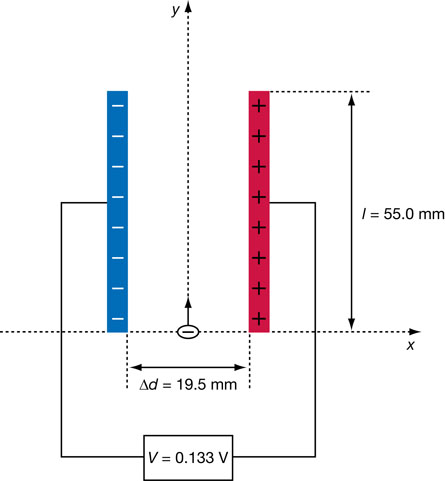
SC 19. The following diagram shows an electron entering the region between two oppositely charged plates. The plates are 55.0-mm long and are separated by 19.5 mm. A potential difference of 0.133 V across the plates generates a uniform electric field in the region between the plates. The electron is given an initial velocity of 8.50 × 10⁵ m/s in the positive ydirection. Use this information to determine the final velocity of the electron when it leaves the region between the plates.
Be sure to begin your solution with a free-body diagram and an analysis of the physics principles that will support your solution.
Self Check Answer
SC 19.
Given
Required
The magnitude and direction of the final velocity of the electron.
Analysis and Solution
Step 1: Free-body diagram and statement of the physics principles.
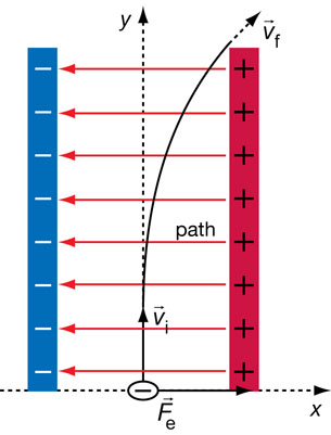
- The electric field between the plates points in the negative x direction.
- Since the particle is negatively charged, the electrostatic force on the particle will act in the positive x direction.
- The electrostatic force will cause the particle to accelerate in the positive x direction. This is in accordance with Newton’s second law of motion.
- Since there is no unbalanced force acting in the y direction, the particle will move with uniform motion in the positive y direction. This is in accordance with Newton’s first law of motion.
- The path of the particle is a parabolic trajectory. This is a consequence of uniform motion in the positive y direction combined with accelerated motion in the positive x direction.
Step 2: Determine the magnitude of the electrostatic force.
Step 3: Determine the magnitude of the acceleration in the positive x direction
Step 4: Determine the time for the particle to travel to the end of the region between the plates. Use the fact that the motion in the y direction is uniform.
Step 5: Determine the final velocity in the x direction.
Step 6: Use the x and y components to find the final velocity. Since the motion in the y direction is uniform vfy = +8.50×10⁵ m/s.
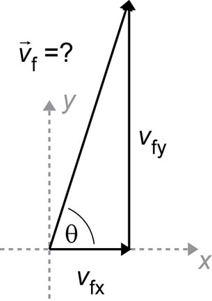
Paraphrase
The final velocity of the electron when it leaves the region between the plates is 8.54×10⁵ m/s [85°].
Module 3: Lesson 6 Assignment
Remember to submit the answer to A 2 to your teacher as part of your Module 3: Lesson 6 Assignment.
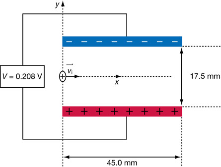
A 2. The following diagram shows a proton entering the region between two oppositely charged plates. The plates are 45.0 mm long and are separated by 17.5 mm. A potential difference of 0.208 V generates an electric field between the plates. The proton is given an initial velocity of 1.35 × 10⁴ m/s in the positive x direction. Use this information to determine the y component of the displacement of the proton when it leaves the region between the plates. (Note: This displacement is how far the proton has moved above or below the x-axis the instant it leaves the region between the plates.)
Be sure to begin your solution with a free-body diagram and an analysis of the physics principles that apply.