Module 5
1. Module 5
1.31. Page 3
Module 5—Wave Theory of Light
Diffraction, Path Difference, and Interference
Path difference can explain interference patterns seen by Thomas Young. Each wave must travel a certain length, along a specific path, from the slit to the distant screen.
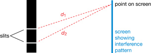
The length from any one point on the screen to each slit is slightly different, as shown in d1 and d2, since the slits are located some distance apart. This means that light leaving both slits must travel slightly different lengths, d1 and d2, to arrive at the same spot on a distant screen. The difference in the path lengths is called the path difference.
Path difference, Δd = |d1 – d2|
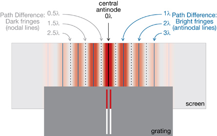
If the path difference to a common point on the screen is an integral number of wavelengths, then the waves arrive at the common point in phase and constructively interferes producing a bright fringe. However, if the path difference is a half-number of waves, then the waves arrive completely out of phase and destructively interfere leaving a dark fringe.
bright fringes: regions of constructive interference along antinodal lines
dark fringes: regions of destructive interference along nodal lines
Path difference explains the interference patterns created by two-slit diffraction. When the light reaches a screen, bright and dark bands are observed. These bands are called interference fringes. Bright fringes (antinodal lines) are regions of constructive interference and dark fringes (nodal lines) are regions of destructive interference. The following image illustrates the fringes and the path differences for the interference pattern created when light is diffracted in a two-slit experiment. Notice that the bright and dark fringes are symmetrical around the central antinode.
 Read
Read
Read “The Interference Pattern” on pages 686–687 of your textbook. Look at “Figure 13.72” to “Figure 13.74” for some great illustrations of the path difference explanation described earlier. These figures will help with SC 1 and SC 2.
 Self-Check
Answer the following questions based on your readings and observations in the previous video and simulations.
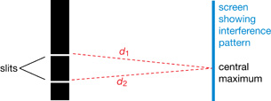
SC 1. Why is there always a bright fringe at the centre of the screen? (This fringe is called the central antinode.)
SC 2. Explain why this central antinode is always the brightest fringe.
Self-Check Answers
Contact your teacher if your answers vary significantly from the answers provided here.
SC 1.
The central antinode is the result of constructive interference. The path length from each hole in the grating to the central antinode is identical so the path difference is zero (as shown in the diagram). Both waves arrive in phase and interfere constructively to produce the bright fringe.
SC 2.
All of the waves arriving at the central antinode are completely in phase, causing complete constructive interference. The other bright fringes will have some destructive interference due to multiple slits or the light is naturally dimmer because it is not the first order maximum, which is the brightest.
Read
Two-slit diffraction patterns can be understood mathematically based on the concept of path length and the wavelength. For example, the location of bright antinodes and dark nodes in the two-slit interference pattern can be used to determine the exact wavelength of the light causing them.
Read pages 687–689 in your textbook for a full derivation of the mathematical relationships.
The interference pattern produced by diffraction through a double slit can be analyzed using the following equation:
![]()
| Quantity | Symbol |
SI Unit |
wavelength |
λ |
m |
slit spacing (separation between slits) |
d |
m |
path difference* |
n |
none (number of wavelengths) |
angle of diffraction (measured from the central antinode) |
(θ) |
degrees |
* Constructive interference (antinodes − bright fringes) occurs when the path difference is a whole number of wavelengths (n = 0, ±1, ±2, ...). Thus, for antinodes or bright fringes: n = 1, 2, 3, 4, ….
Destructive interference (nodes − dark fringes) occurs when the path difference is offset by half a wavelength (n = ±0.5, ±1.5, ±2.5, ...). Thus, for nodes or dark fringes: n = 0.5, 1.5, 2.5, 3.5, ….
Example Problem 1.
Light with a wavelength of 457 nm is shone through two slits separated by 0.20 mm.
a. What is the angle of diffraction to the second bright fringe (n = 2)?
Given
Required
the angle of diffraction
Analysis and Solution
Paraphrase
The angle of diffraction is 0.26° from the central bright fringe.
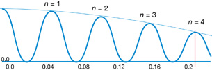
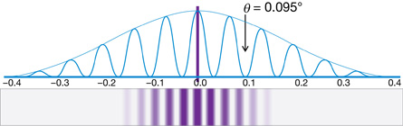
The light producing the second order bright fringe, or n = 2 antinode, is diffracted through a 0.26° angle as it exits the two slits. A simulation can be used to verify this calculation and visualize the interference pattern near the n = 2 bright antinode.
Open the Diffraction Grating simulation and set the slit width, wavelength, and slit count as indicated in the following screen shot.
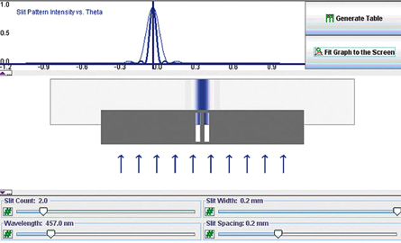
While holding down the Ctrl key, you can drag out a region of the intensity graph to zoom in. You may do this a number of times to get an appropriate scale, where the 0.26° angle is visible.
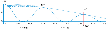
You can see that the n = 2 region is located 0.26° from the central antinode.
b. What is the angle of diffraction to the second dark fringe?
Given
Remember that destructive interference, dark fringes, have n values that end in .5. The first dark fringe is 0.5, so the second one is 1.5.
Required
the angle of diffraction to the second dark fringe
Analysis and Solution
Paraphrase
The angle of diffraction to the second dark fringe is 0.20°. If you look at the previous screen shots, you will see that the simulation gives the same result for n = 1.5.
 Module 5: Lesson 6 Assignment
Remember to submit your answer to A 2 to your teacher as part of your Module 5: Lesson 6 Assignment.
A 2. Using the Diffraction Grating simulation, set the slit count to 2.0, the wavelength to 550.0 nm, the slit width to 0.1 mm, and the slit spacing to 0.2 mm. Observe how the following changes affect the interference pattern.
- decreasing the wavelength
- increasing the wavelength
- decreasing the slit width
- increasing the slit width
- decreasing the slit spacing
- increasing the slit spacing
Summarize your observations on how the wavelength, slit width, and slit spacing affect the interference pattern in the simulation in a table or graphic organizer of your choice.
Self-Check
SC 3. If some light passes through two slits, separated by 0.33 mm, and the first dark fringe is located 0.035° from the central antinode, what is the wavelength of the light? Show the calculation and check your answer with the simulation.
SC 4. Blue light of wavelength 465 nm is incident on a double slit where the slits are spaced 0.5 mm apart and are 0.05 mm wide. At what angle of diffraction will the fourth order antinodal line appear? Show the calculation and check your answer with the simulation.
Self-Check Answers
Contact your teacher if your answers vary significantly from the answers provided here.
SC 3.
Required
the wavelength of the light
Analysis and Solution
Paraphrase
The wavelength is 4.0 × 10⁻⁷ m.
SC 4.
Given
Required
the angle of diffraction to the fourth order antinodal line
Analysis and Solution
Paraphrase
The angle of diffraction to the fourth order antinodal line is 0.21°.
 Try This
TR 2. Radiation of 400 nm passes through two slits and produces the following interference pattern. Given the angle of diffraction for the second order dark fringe, determine the slit separation. Show the calculation and check your answer with the simulation.
Read
As you will have noticed from each of the noted scenarios, the angle of diffraction is always very small, making it difficult to measure accurately in many experimental conditions. In such cases, a second equation is used that approximates the small angle using a ratio of the distance separating the screen and slits to the distance between any two antinodes. For very small angles, use the equation sin θ = x/L.
Read the “infoBIT” on page 690 of your textbook for the derivation of the small angle approximation.
The interference pattern produced by diffraction through a double slit can be analyzed using the following equation.
![]()
| Quantity | Symbol |
SI Unit |
wavelength |
λ |
m |
distance from central antinode to antinodal line |
x |
m |
slit spacing (separation) |
d |
m |
path difference* |
n |
none (number of wavelengths) |
distance between slits and screen |
L |
m |
* Constructive interference (antinodes − bright fringes) occurs when the path difference is a whole number of wavelengths (n = 0, ±1, ±2, …). Thus, for antinodes or bright fringes: n = 1, 2, 3, 4, ….
* Destructive interference (nodes − dark fringes) occurs when the path difference is offset by half a wavelength (n = ±0.5, ±1.5, ±2.5, …). Thus, for nodes or dark fringes: n = 0.5, 1.5, 2.5, 3.5, ….
Work through “Example 13.9” on page 691 of the textbook.
Try This
TR 3. Complete “Practice Problems” 1–3 on page 691 of the textbook.
Read
diffraction grating: an optical component that has a surface covered by a regular pattern of parallel lines or grooves that are usually separated by a distance comparable to the wavelength of light
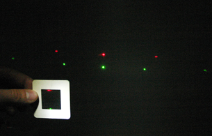
The tightly spaced concentric rings on a CD or DVD from the Get Focused section of this lesson are an example of a diffraction grating.
The equations that describe a two-slit experiment are equally useful for gratings, since they only rely on the spacing between any two slits. Dividing the width of the grating by the total number of lines or spaces on it gives the distance between any two lines, which is the slit separation that can be used with any diffraction equation.
Read “Diffraction Gratings” and “Example 13.10” on pages 692–693 of your textbook.
Try This
TR 4. Complete “Practice Problems” 1–3 on page 693 of the textbook.
Module 5: Lesson 6 Assignment
Remember to submit your answers to A 3, A 4, and A 5 to your teacher as part of your Module 5: Lesson 6 Assignment.
A 3. A scientist is double-checking the wavelength of a new laser. The scientist sets up a diffraction grating with 5.00×10⁻⁶ m between slits, in front of the laser 1.50 m in front of a screen. The scientist measures the distance from the central maximum to the second bright fringe, which is 0.330 m. What is the wavelength of the laser?
A 4. As part of a laser light show, the technician is adjusting a diffraction grating. A green laser with a wavelength of 532 nm is shone on a diffraction grating with 2700 lines/cm. The screen is 35 m from the diffraction grating.
- What is the distance between the slits of the diffraction grating?
- How far from the central maximum will the bright fringe be?
A 5. A student is looking at a monochromatic light source and is looking for the third bright fringe. The light has a wavelength of 625 nm and has passed through a diffraction grating with a slit separation of 2.80×10⁻⁶ m. At what angle should the student look for the third bright fringe?
Try This
Read “Inquiry Lab” on pages 694–695 of your textbook.
A student performs the “Inquiry Lab” and gathers the following data.
Light |
Left |
Right |
Red |
0.214 m |
0.209 m |
Green |
0.150 m |
0.152 m |
Blue |
0.135 m |
0.139 m |
TR 5. Do “Analysis” questions 1 to 4 on page 695 in your textbook using the results from the previous data.
Read
polarization: the production of a state in which the plane of the electric field for each electromagnetic wave occurs only in one direction
The purpose of Thomas Young’s experiment was to demonstrate the wave nature of light. Polarization gave further evidence to support the wave model of light.
Read pages 695–696 of your textbook to find out about polarization. Then view the animation Polarization.
Self-Check
SC 5. What part of an electromagnetic wave does the polar filter affect?
SC 6. Polarized sunglasses are popular with people who fish and drive boats. Why are polarized sunglasses popular with those groups of people?
SC 7. The liquid crystal display (LCD) used on calculator screens, cellular phones, MP3 players, LCD TVs, and computer projectors use polar filters to block some colours and let other colours be projected onto the screen. What is a possible problem if you wear polarized sunglasses and attempt to use an LCD product?
Self-Check Answers
Contact your teacher if your answers vary significantly from the answers provided here.
SC 5. The polar filter absorbs the electric field; however, you can’t have a magnetic field without an electric field so the wave is stopped by the filter when the electric field is not parallel to the slits of the filter.
SC 6. The polar filter absorbs the horizontally polarized light reflected from the water that causes the most irritating glare. Without the glare, it is much easier to see what is under the water, be it a submerged hazard or a fish. Avoiding glare causes less eyestrain when outside near reflective surfaces.
SC 7. If the polar lens on the sunglasses lines up at 90° to the polar filter in the LCD, then the picture could be colour distorted or completely invisible.
 Discuss
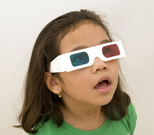
© Jesse Kunerth/shutterstock
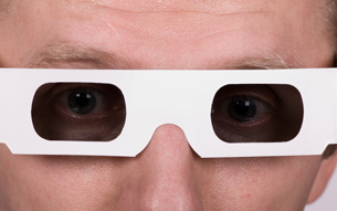
© Andrew Buckin /shutterstock
3-D (three-dimensional) movies are popular again at movie theatres. The technology uses the fact that we have binocular vision because we use two eyes that each takes a picture of the world at a slightly different angle. Your brain assembles the two pictures to create a three-dimensional view of the world. You can test this by looking at something and closing one eye and then the other. You will see the same object but from a slightly different angle.
In the 1950s and 1960s, 3-D movies were developed that projected a red-coloured version of the movie and a blue-coloured version. The audience members wore a pair of cardboard glasses with a blue lens to block the blue version and a red lens to block the red version (as in the photo). In this way, each eye saw only one version of the picture from its perspective.
The viewer’s brain interpreted this as a 3-D image of objects coming out of the screen. Unfortunately, the colours were often distorted because of the colour filters. If you buy a DVD of a 3-D movie to watch on your home TV, this colour, filtering technology creates the 3-D effect.
Today in theatres, however, polar filter glasses and two projectors are used to create the 3-D effect. The big advantage is that the polar filters don’t distort the colours of the movie.
D 1. Using what you know about polar filters, explain how polarized glasses and two projectors can be used to create a 3-D picture. Post your answer in your discussion area.
D 2. Read what other students have suggested, and think about how you can use this information to improve your answer.
Module 5: Lesson 6 Assignment
Remember to submit your answer to D 3 to your teacher as part of your Module 5: Lesson 6 Assignment.
D 3. Improve your answer to D 1, and state what improvements you made to your solution and why.
Discussion Scoring Guide
| Principles involved: polarized light and filters | ||||
Criteria |
Level 1 |
Level 2 |
Level 3 |
Level 4 |
Knowledge |
||||
Demonstrates a vague and sometimes incorrect understanding of the physics principles involved. Obvious irrelevant or missing information. |
Demonstrates a basic understanding of the physics principles involved. May exhibit minor mistakes or vague information or application to the situation. |
Demonstrates a good understanding of the physics principles involved and applies them properly to the given situation. All necessary information is given. |
Demonstrates a superior understanding of the physics principles involved and their application to the situation. All applications are considered in detail. |
|
Reflection |
||||
The post shows reflection on one’s own and other students’ work. Contributes to the group discussion. |
Does not make an effort to participate. Seems indifferent to discussion. |
Occasionally makes meaningful reflections on the group’s efforts or discussions. Marginal effort is shown to become involved with the group or discussion. |
Frequently makes meaningful reflections on the group’s efforts and presents relevant viewpoints for consideration by the group. Interacts freely with group members. |
Regularly attempts to motivate the group discussion and delve deeper into concepts. Interacts freely and encourages all group members. |
Content and presentation of discussion summary |
||||
The information is logically arranged in a clear and concise manner. |
The information is poorly organized with many concepts implied. Irrelevant or rambling sentences make reading difficult. |
The information is somewhat organized with implied concepts. Excessive words or awkward sentences are used, which hinder reading. |
The information is well-organized and logically arranged. All concepts are explicitly explained. There are a few awkward but understandable sentences. |
The information is well-organized and very easy to understand. Well-worded sentences make reading pleasurable. |