Module 5
1. Module 5
1.34. Module Summary/Assessment
Module 5—Wave Theory of Light
 Module Summary and Assessment
Module 5: Wave Theory of Light is all about proving that light is a wave and not a particle. Throughout the module, you studied the key experiments that showed EMR is a wave by examining its characteristics:
- production
- speed and propagation
- reflection
- refraction
- diffraction and interference
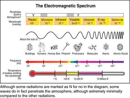
Lesson 1 began by looking at the electromagnetic spectrum and how EMR is produced, starting with low-energy radio waves, going up to the rainbow of visible light, and continuing up to high-energy gamma rays. The spectrum is organized by the wavelength and frequency of the EMR wave. The EMR wave is a combination of changing electric and magnetic fields at right angles to each other. They are created by accelerating charges and can induce currents in antennas as a radio does.
All of the wave properties of EMR were summarized by Maxwell’s electromagnetic theory and later proved by Heinrich Hertz, who used a spark gap to create the artificial EMR, now called radio waves. You discovered that radio waves are very common today. AM/FM radios, cellphones, garage-door openers, and cordless phones operate in the radio range of the spectrum.
Adapted from image courtesy of NASA
Lesson 2 was about the speed of light and its propagation. You learned that several methods have been used to measure the speed of light. As the technology improved, the experimental results improved, culminating with Michelson’s rotating mirror experiment that produced the current value of c = 3.00 × 10⁸ m/s. You also learned how to measure the speed of light using the interference pattern of the microwaves in a microwave oven. The speed of light further verified Maxwell’s theory of electromagnetic waves.
Lesson 3 was about exploring reflection and how it supports the wave nature of EMR. You saw how specular and diffuse reflection of light waves can be illustrated using ray diagrams, which identify the path of the light waves using arrows (as shown in these two diagrams).
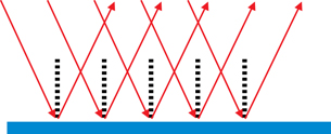
specular reflection
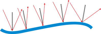
diffuse reflection
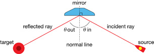
You learned that ray diagrams are based on the law of reflection, which states that the angle of reflection relative to the normal line is equal to the angle of incidence. Ray diagrams and equations are used to predict the position and characteristics of images in both plane (flat) and curved mirrors. You saw how reflection and mirrors are used in many of today’s modern technologies, such as digital light processing, telescopes, and satellite dishes.

In Lesson 4 you learned that refraction supports the wave model of light. Refraction occurs when a light wave changes speed when the wave transitions from one medium into another and changes directions (as shown in the diagram on the left). You learned that the index of refraction is based on the velocity of light in a medium and how Snell’s Law uses the index of refraction to mathematically describe the change in direction of the light as it changes media, velocity, and wavelength.
![]()
When light goes from a high-index medium to a low-index medium and the angle of incidence is equal to or larger than the critical angle, the light will experience total internal reflection instead of refraction. The light will stay within the higher index medium. One application of this reflection is high-speed communication networks using light instead of electricity, which can occur because total internal reflection prevents light from exiting the side of fibre optic cables. In nature, refraction causes rainbows to form as the white light entering raindrops is split into the visible light spectrum because the different wavelengths of visible light refract at slightly different angles.
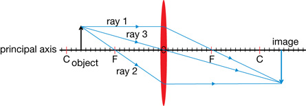
This led to Lesson 5 and the application of refraction with thin lenses. To explore thin lenses, you drew light ray diagrams and solved them mathematically, similar to the curved mirrors. The thin lenses are, for example, used for glasses, telescopes, and microscopes.
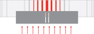
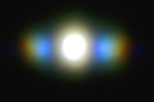
The final support of the wave nature of light was diffraction and polarization in Lesson 6. You learned that diffraction is the interference of light after it passes through a system of slits as exhibited by Young’s double-slit experiment. The interference pattern (shown in the picture that follows) could only be explained by using wave theory and is shown mathematically in the equations: ![]() and
and ![]() . The diffraction interference pattern can be seen in the rainbow of light diffracted by everyday objects like CDs and DVDs.
. The diffraction interference pattern can be seen in the rainbow of light diffracted by everyday objects like CDs and DVDs.
Finally, the wave nature of light was demonstrated using polar filters that block different amounts of light depending on the filters’ orientation. Polar filters absorb the electric field of the EMR and only allow EMR through that is vibrating in one plane. If the filters are oriented at 90° to each other, they absorb all of the wave energy. They are commonly used in sunglasses or camera filters to block glare from reflected surfaces.
Module 5 showed you that the wave nature of EMR is supported by the production, speed, propagation of light, reflection, refraction, diffraction, interference, and polarization of light.
The wave nature of EMR will be built upon in Module 6 where you will be introduced to the principle of wave-particle duality of EMR and the quantum theory of physics.
Module Assessment
Question 1
Use the following information to answer this graphing question.
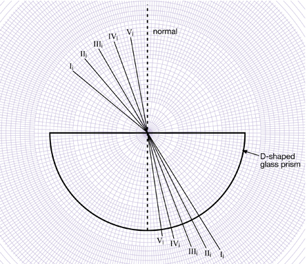
You will complete the analysis of the following investigation to determine the index of refraction of a glass prism shaped like the letter D.
Materials
- polar graph paper
- D-shaped glass prism
- laser
- small sheet of paper
Procedure
- Place the D on the polar graph paper so that the midpoint of the straight side of the D is centred.
- Shine the laser toward the straight side of the D so that it hits the midpoint exactly. To make observations easily, hold the laser so that the beam shines along the polar graph paper. This is the incident beam.
- Use the small sheet of paper as a screen to observe the refracted beam after it leaves the D.
- Repeat steps 2 and 3 for several angles of incidence in air.
Observations
The polar graph paper with the locations of the D and five beams is shown.
| Observations | Analysis | ||
| Angle of Incidence in Air (degrees) | Angle of Refraction in Glass (degrees) | Sine of Angle of Incidence | Sine of Angle of Refraction |
| 50.0 | 33.0 | ||
| 40.0 | 27.0 | ||
| 30.0 | 21.0 | ||
| 20.0 | 14.0 | ||
| 10.0 | 7.0 | ||
Analysis
Determine the index of refraction of the glass. In your response,
- complete the table by calculating the sines of the angles
- provide a graph of the sine of the angle of refraction as a function of the sine of the angle of incidence
- determine the slope of the graph
- explain the physics significance of the slope
Marks will be awarded based on your graph and on the mathematical treatment of the physics you used to solve this problem.
Graphing Question Scoring Guide
Question 2
Answer the following holistic question.
You have seen two ways to produce a spectrum from white light. Compare and contrast the visible spectrum produced by diffraction gratings with those produced by triangular prisms.
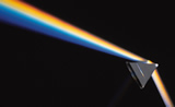
This spectrum was produced by a triangular prism.
© 2009 Jupiterimages Corporation
This spectrum was produced by a diffraction grating.