Module 5
1. Module 5
1.12. Lesson 3
Module 5—Wave Theory of Light
Lesson 3—Reflection
 Get Focused
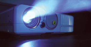
© Mikolaj Tomczak/shutterstock
This projector is an application of DLP technology.
Have you ever wondered how a small box with one really bright, white light can make the most brilliant, colourful images come to life on a movie screen? Many computer-projection systems and rear-projection televisions use digital light processing (DLP) to generate high-definition colour images that can change in an instant. At the heart of a DLP television or projection system is a digital micromirror device (DMD).
About the size of a postage stamp, a DMD contains several hundred thousand microscopic mirrors arranged in a rectangular array. Each microscopic mirror is a semiconductor-based light switch that controls one pixel in the image (a pixel is a single point in an image). The microscopic mirror can be orientated in one of two ways. In one orientation, the micromirror will reflect light from the bulb through the lens and onto a screen to turn the pixel on. In the other orientation, the microscopic mirror will reflect light away from the lens to an absorber, effectively turning that pixel in the image off. Various shades of light are achieved by continuously changing the orientation of the micromirrors between on and off. If more time is spent in the on position, the pixel becomes brighter.
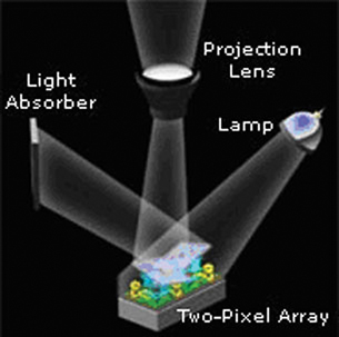
© Courtesy of Texas Instruments
Colour is introduced by placing a rotating disk with colors between the bulb and the DMD. A computer then controls each micromirror orientation so that the desired colours are reflected through the projection lens at precise times as the colour wheel rotates. The various colour images appear so quickly they appear to merge into one, fluid, full-colour image. You can learn more about the “digital micromirror device” by using these terms in an Internet search.
In digital light processing, the orientation of a mirror determines which path the light will follow. It does this in a very predictable way, making it possible to determine the orientation of the lamp, light absorber, and projection lens. The placement of these components is based on the behaviour of the light as the light reflects from the mirror according to the law of reflection. You will look at how the law of reflection can be expressed graphically using light ray diagrams and, mathematically, using equations.
In this lesson you will answer the following essential questions:
- What is regular and diffuse reflection?
- What is the law of reflection?
- How do I draw a ray diagram, and what does it represent?
- How are images formed in flat and curved mirrors, and how are ray diagrams used to predict and explain their characteristics?
 Module 5: Lesson 3 Assignment
Your teacher-marked Module 5: Lesson 3 Assignment requires you to submit responses to the following questions:
- Laboratory—LAB 1, LAB 2, LAB 3, and LAB 4
- Assignment—A 1, A 2, A 3, A 4, and A 5
- Discuss—D 1
The other questions in this lesson are not marked by the teacher; however, you should still answer these questions. The Self-Check and Try This questions are placed in this lesson to help you review important information and build key concepts that may be applied in future lessons.
After a discussion with your teacher, you must decide what to do with the questions that are not part of your assignment. For example, you may decide to submit to your teacher the responses to Try This questions that are not marked. You should record the answers to all the questions in this lesson and place those answers in your course folder.