Lesson 5
| Site: | MoodleHUB.ca 🍁 |
| Course: | Math 30-3 SS |
| Book: | Lesson 5 |
| Printed by: | Guest user |
| Date: | Monday, 3 November 2025, 4:51 AM |
Description
Created by IMSreader
1. Lesson 5
Module 5: Geometry
Lesson 5: Multiple Transformations
Focus

iStockphoto/Thinkstock
Translations, reflections, dilations, and rotations can all be useful in construction. Imagine what the plan for the light and background in the picture looked like. Can you see the different transformations in the picture? Sometimes a single transformation is not enough to describe how an object changes. Using two or more transformations in sequence can add to the versatility of transformations.
In this lesson, you will explore how two transformations can be used one after the other.
Lesson Outcomes
At the end of this lesson you will be able to
- perform multiple transformations on two-dimensional and three-dimensional objects
- determine the transformations used, given an original figure and a transformed figure
Lesson Question
You will investigate the following question:
- How can multiple transformations be used to change a figure?
Assessment
Your assessment may be based on a combination of the following tasks:
- completion of the Lesson 5 Assignment (Download the Lesson 5 Assignment and save it in your course folder now.)
- course folder submissions from Try This and Share activities
- work under Project Connection
Materials and Equipment
- graph paper
- scissors
1.1. Discover
Module 5: Geometry
Discover
In the previous lesson, you explored four different types of transformations: translations, reflections, rotations, and dilations. In the next activity, you will explore how multiple transformations can be used.
Try This 1

Chad has drawn an emblem for his band “Angry Bones.”
- What transformation or combination of transformations could Chad have used to place the bottom fish skeleton once he drew the top one?
- Print or sketch the Angry Bones Template. Cut out the two fish templates on the right side.
Describe how you can use the template to test your prediction from part a. - Test your prediction using the template. How accurate is your test?
Suppose Chad told you he chose some important points on the illustration, reflected them over the x-axis, and then rotated the diagram 90° counterclockwise about the origin to determine the new positions.
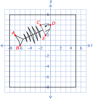
- Check to see if Chad’s instructions are correct. Start by completing the following table.

Original Point
Original Point Reflected Across the x-axis
Reflected Point Rotated 90° Counterclockwise
A(−7, 2)
A′(−7, 2)
A″(−7, 2)
B(−6, 0)
C(−2, 4)
D(0, 4)
E(−1, 2)
- Plot the points that have been reflected and rotated to decide if Chad’s instructions are correct. If you printed the template, use it to plot your points.
- Predict whether the instructions “rotate the illustration 90° counterclockwise about the origin and then reflect the points vertically” gives the same picture as the instructions Chad gave.
- Complete a table like the one shown.
Original Point
Original Point Rotated 90° Counterclockwise
Rotated Point Reflected Across the x-axis
A(−7, 2)
B(−6, 0)
C(−2, 4)
D(0, 4)
E(−1, 2)
- Plot the rotated and reflected points to decide if the two sets of instructions are equivalent. If you printed the template previously, use it to plot your points.
- What can you conclude about the order of transformations applied to a figure?
![]() Save your responses in your course folder.
Save your responses in your course folder.
1.2. Explore
Module 5: Geometry
Explore
When transforming objects, it is sometimes useful to have a physical representation to manipulate, such as the paper cutouts you used in Try This 1. Do you think this strategy would work for all transformations? ![]()
In the previous lesson, you explored how four different kinds of transformations can each be used to manipulate a figure. It is possible to use more than one of these transformations on a figure.
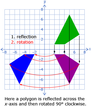
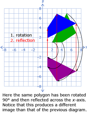
In Try This 1, Chad used a reflection and a rotation to arrange his fish skeletons. You may have noticed that when multiple transformations are used, the order is important. Chad used a reflection and then a rotation. If the same reflection and rotation are used, but in the opposite order, the resulting images are usually different from the ones produced in the original order.
When completing multiple transformations, treat each as a separate step. Complete the first transformation and then use those new points as a starting point for the next transformation.
1.3. Explore 2
Module 5: Geometry
In the next activity, you will look at how a translation can be combined with a dilation.
Try This 2
Jenara is installing a bathroom sink, and she needs to pass two PEX waterlines and an ABS drainpipe through a wall. The PEX waterline has a nominal size of ![]() in and will require a hole of
in and will require a hole of ![]() in. The ABS drainpipe has a nominal size of 2 in and will require a hole of 2.5 in.
in. The ABS drainpipe has a nominal size of 2 in and will require a hole of 2.5 in.
- Determine a scale factor that could be used to dilate the 2.5-in hole to the
 -in hole.
Jenara has drawn a 2.5-in hole in the wall where she would like to position the ABS drainpipe. Jenara plans to put the centre of one waterline hole 2 in left and 3 in above the centre of the drain line. She plans to put the other waterline hole 2 in right and 3 in above the centre of the drain line.
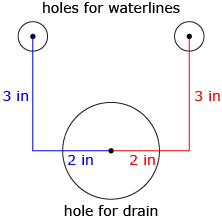
Suppose Jenara has drawn the drainpipe on a coordinate grid and plans to use a translation and a dilation to draw the circles required for the waterlines.
- To draw the waterline holes, do you expect it will be easier to translate and then dilate or to dilate and then translate the drain-line hole? Explain your reasoning.
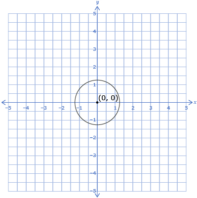
- Sketch the diagram using the Grid Paper Template located in the course Toolkit or grid paper that you may already have. Draw four points on the circle that you can use to help with the transformation. Label the points A, B, C, and D.
- Complete tables like the ones shown for the right waterline hole using the points you determined in question 3.
Point
Original Point Dilated by Factor from Question 1
Dilated Point Translated
A(__, __)
B(__, __)
C(__, __)
D(__, __)
Point
Original Point Translated
Translated Point Dilated by Factor from Question 1
A(__, __)
B(__, __)
C(__, __)
D(__, __)
- If the two tables in question 4 resulted in different coordinates, which do you expect to be correct? Use what you think are the correct coordinates to draw the coordinates for the right waterline on the grid.
- Describe at least two ways a transformation or transformations can be used to determine the coordinates for the left waterline hole.

- Use one of the methods you described in question 6 to draw the left waterline hole.
![]() Save your responses in your course folder.
Save your responses in your course folder.
Share 1
With a partner or in a group, discuss the following questions.
- Describe another method Jenara could have used to accurately make the holes.
- Describe some advantages and disadvantages of using transformations to draw the positions of the holes in this scenario.
![]() If required, place a summary of your discussion in your course folder.
If required, place a summary of your discussion in your course folder.
1.4. Explore 3
Module 5: Geometry
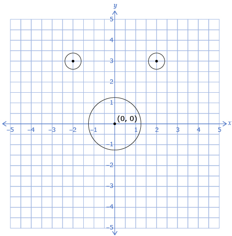
In Try This 2, you saw that it is possible to perform a dilation followed by a translation to produce an image that has a different size and position than the original. The diagram you produced may have looked like the following.
Transformations tend to be most useful when you need to accurately produce a new object that is similar to an existing object, especially if the object is complex. There are multiple ways to use transformations to produce a shape, and some are easier than others. For example, it may have been easier for Jenara to translate the centre of the drain hole to determine the centres of the waterline holes. She could have then used a ![]() -in drill bit and a 2.5-in drill bit and centred on these points to make the holes.
-in drill bit and a 2.5-in drill bit and centred on these points to make the holes.
Self-Check 1
Answer “Build Your Skills” questions 1, 2, 4, and 6 from pages 238 to 240 of the textbook. Answer
1.5. Explore 4
Module 5: Geometry
In the next activity, you will determine the transformations used to produce some new images from an original shape.
Try This 3
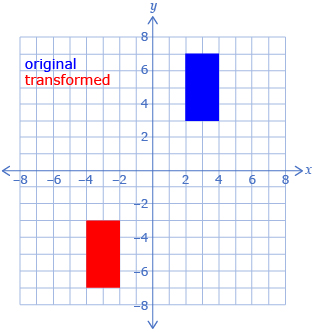
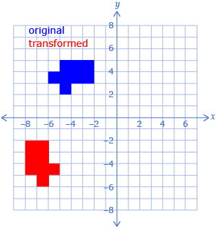
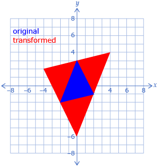
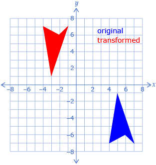
In the following table, each transformed object was made by using two transformations on the original shape.
For each diagram, determine two possible sets of transformations that would produce the red shape from the blue shape. The Transformations Template provided may help you determine the transformations. The table might also help you organize your thinking.
1.
|
Possible Set of Transformations 1:
Possible Set of Transformations 2:
|
2.
|
Possible Set of Transformations 1:
Possible Set of Transformations 2:
|
3.
|
Possible Set of Transformations 1:
Possible Set of Transformations 2:
|
4.
|
Possible Set of Transformations 1:
Possible Set of Transformations 2:
|
![]() Save your responses in your course folder.
Save your responses in your course folder.
Share 2
With a partner or in a group, discuss the following questions.
- Compare the strategies you used to determine the transformations used.
- Which strategy seemed most reliable?
- Which strategy seemed most efficient?
- Which set of transformations from Try This 3 did you find the most difficult to determine? Why do you think this was the case?
![]() If required, place a summary of your discussion in your course folder.
If required, place a summary of your discussion in your course folder.
1.6. Explore 5
Module 5: Geometry
Determining which transformations were used to produce a new shape can be tricky. One possible strategy is to pick a particular point on the original shape and determine which transformations could take it to the corresponding point on the transformed shape. Then check to see if that set of transformations works for the other points as well.
Self-Check 2
![]()
- Complete “How Did it Get There?” questions 2 and 3 on page 236 of your textbook. Answer
- Answer question “Build Your Skills” question 3 from page 239 of your textbook. Answer
So far all of the transformations you have examined in this module have been two-dimensional. It is also possible to use transformations in three dimensions. In the next activity, you will predict the transformation used in a three-dimensional setting.
Try This 4
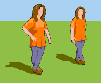
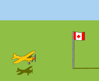
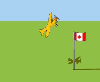
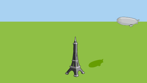
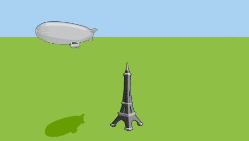
Look at the following diagrams. Each diagram uses a transformation you have learned, but in three dimensions. Explain what transformation each diagram represents by completing a table like this one.
|
|
|
|

![]() Save your responses in your course folder.
Save your responses in your course folder.
1.7. Explore 6
Module 5: Geometry
In Try This 4, you may have noticed that three-dimensional transformations are very similar to two-dimensional transformations, but they are sometimes a bit harder to see.
- The fish represented a dilation, because the fish were the same except one was larger than the other.
- The girls represented a reflection. You can imagine this picture being made using the girl on the left and a mirror that is to the right and slightly behind her.
- The plane has been rotated. If the pattern continued, the plane would fly in a circle.
- Finally, the blimp is a translation. It is the same object in a different position. Although the blimp looks bigger, it is because it is closer and viewed from a different angle. The blimp did not change size while travelling.
Self-Check 3
1.8. Connect
Module 5: Geometry
Complete the Lesson 5 Assignment that you saved in your course folder at the beginning of the lesson. Show work to support your answers.
![]() Save your responses in your course folder.
Save your responses in your course folder.
Project Connection
You are now ready to apply your knowledge of transformations to Module 5 Project: Designing a Yard. Go to the Module 5 Project, and complete Part 2: Designing a Patio Garden.
![]() Save your responses in your course folder.
Save your responses in your course folder.
1.9. Lesson 5 Summary
Module 5: Geometry
Lesson 5 Summary

Digital Vision /Thinkstock
Sometimes more than one transformation is required to describe how an object changes. The order of a series of transformations is important. If the order is changed, it will often produce a different final image. To use successive transformations, complete the first transformation and use the image produced as a starting point for the next transformation.
Transformations can be completed in two dimensions and in three dimensions. Typically, two-dimensional transformations are easier to work with.