Module 5
| Site: | MoodleHUB.ca 🍁 |
| Course: | Biology 30 [5 cr] - AB Ed copy 1 |
| Book: | Module 5 |
| Printed by: | Guest user |
| Date: | Thursday, 18 September 2025, 4:30 PM |
Description
Created by IMSreader
Table of contents
- 1. Module 5
- 1.1. Lesson 1
- 1.2. Page 2
- 1.3. Page 3
- 1.4. Page 4
- 1.5. Page 5
- 1.6. Lesson 2
- 1.7. Page 2
- 1.8. Page 3
- 1.9. Page 4
- 1.10. Page 5
- 1.11. Lesson 3
- 1.12. Page 2
- 1.13. Page 3
- 1.14. Page 4
- 1.15. Page 5
- 1.16. Lesson 4
- 1.17. Page 2
- 1.18. Page 3
- 1.19. Page 4
- 1.20. Page 5
- 1.21. Lesson 5
- 1.22. Page 2
- 1.23. Page 3
- 1.24. Page 4
- 1.25. Page 5
- 1.26. Lesson 6
- 1.27. Page 2
- 1.28. Page 3
- 1.29. Page 4
- 1.30. Page 5
- 1.31. Module 5 Summary
1. Module 5
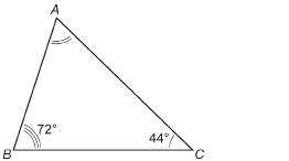
Module 5: Angles
Module 5 Introduction
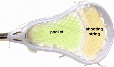
© Zedcor Wholly Owned/PhotoObjects.net/Thinkstock
The roots of the game of lacrosse have been traced to the First Nations cultures of the Eastern Woodlands. The game originated about 1000 years ago. Lacrosse was recognized by an act of Parliament in 1994 as Canada’s national summer sport. Lacrosse is a vigorous game enjoyed by men and women across Canada!
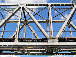
The graphic shown is of a contemporary lacrosse stick. The webbing of the geometric design changes from the pocket to the shooting string to make it easier to either cradle or shoot the ball. The parallel lines, four-sided figures, and the repeated angles in the webbing illustrate that geometry plays an important role in sports equipment.
In this module you will explore the geometry of angles. In particular, you will investigate how they are defined, measured, classified, duplicated, and bisected. As well, you will explore relationships among the angles formed when two parallel lines are cut by a third line. In each case, you will apply definitions and relationships to solve a variety of practical problems. Some of these problems will include sports or the arts—the focus of the Unit 3 Project.
In this module you will be further developing your skills, so be prepared to be active as you investigate the following questions:
-
How are angles defined, measured, classified, duplicated, and bisected?
-
What are the relationships among the angles formed when two parallel lines are cut by a third line?
Save a copy of the Module 5 Glossary in your course folder now.
The Module 5 Glossary is a list of all of the new terms you will see in the lessons. Each time you see a definition, open your copy of the Glossary. Use the space available to add notes or drawings to help your understanding. You will be able to use your personal Glossary as a study tool.
1.1. Lesson 1
Module 5: Angles
Lesson 1: Sketching and Measuring Angles
Focus

© Vitaly M/shutterstock
Cue sports, such as snooker, require a steady hand, practice, and an eye for angles. What separates the novice and the skilled player is the ability to predict how the billiard balls will behave when struck and when they carom off the cushions. Spaced at regular intervals along the table’s perimeter are diamond shapes, which assist a player in assessing possible angles to line up the shot. When a cue ball strikes another ball, what is the largest possible angle the struck ball can be deflected from the line along which the cue ball was travelling?
Lesson Questions
In this lesson you will explore these questions:
-
How can you sketch and describe angles of various measures?
-
How are referents used to estimate the measure of a given angle?
-
How is the protractor used to measure angles in a variety of orientations?
Assessment
You will complete the Lesson 1 Assignment Booklet for assessment. Download the Lesson 1 Assignment Booklet and save it in your course folder now. You will receive instructions on how to complete the Assignment Booklet later in the lesson. You will also be prompted to start working on the Unit 3 Project.
There are other activities that you will complete throughout this lesson. It is important to complete all activities and save them in your course folder. Your teacher may ask to see your work at any time.
The lesson provides you with opportunities to investigate, review examples, and practise the knowledge and skills you are learning. In Self-Check activities you can compare your answers to see if you are on track. If you are having difficulty with concepts or calculations, contact your teacher.
Required Materials and Equipment
For this lesson you will need
-
a protractor
-
a ruler
-
several blank sheets of paper
-
a calculator
1.2. Page 2
Module 5: Angles
Get Started
To move further through this lesson and module, you will need to be able to measure and draw angles. In this part of the lesson you will review the parts of an angle and check how to sketch and measure angles using a protractor.
 Try This
The common endpoint of the arms of the angle is the vertex of the angle.
Work with a partner, if possible.
In previous math courses you drew and measured angles of various sizes.
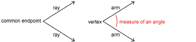
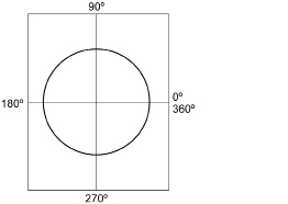
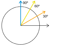
The measure of an angle is commonly given in degrees. There are 360 degrees in one rotation. Use the animation “Angle” to see all the angles possible in one 360-degree rotation.
Try This
Did You Know?
The peoples of the Middle East and ancient India divided the circle into 360 parts. This was, in part, because there are approximately 360 days in a year and the stars move in the sky in a great circle that takes a year to complete. Also, 360 is much more convenient to use than 365. Besides 1 and 360, the number 360 can be divided evenly by 2, 3, 4, 5, 6, 8, 9, 10, 12, 15, 18, 20, 24, 30, 36, 40, 45, 60, 72, 90, 120, and 180. Arithmetic is just simpler using 360.
Work with a partner, if possible.
You will need your protractor and a straight edge.
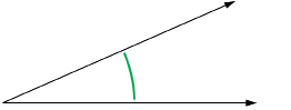
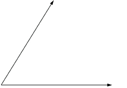
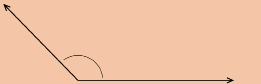
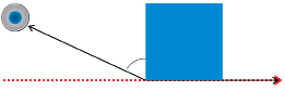
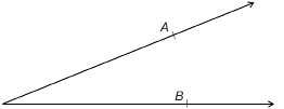
First review how to use your protractor. You will see two scales. The green or upper scale is for angles oriented to the right like the following graphic.
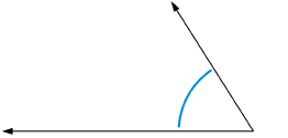
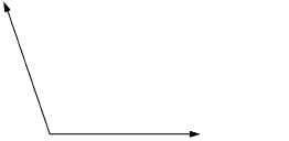
The blue or lower scale is for angles oriented to the left like the following graphic.
Use the applet “eProtractor” to practise making angles. Watch the angle measurements changing as you drag the coloured dot.
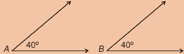
TT 1. You and your partner should measure each of the following four angles separately, and then check each other’s work for accuracy. Record all measurements to the nearest degree.
TT 2. Draw each angle from the measurements that follow. Draw the angles in parts a and b opening to the right, as in TT 1.a. and b. Draw the angles in parts c and d opening to the left, as in TT 1.c. and d. Save your diagrams.
Hint: You may find the “eProtractor” helpful. You viewed this applet earlier in the lesson.
- 49°
- 149°
- 16°
- 127°
 Share
Share
Once you have completed the activities in Get Started, discuss your answers with your partner, or collaborate by electronic messaging with at least two other Mathematics 10-3 students.
Discuss how some people can have different angle measurements when they are using the same tools. Identify some reasons why this might happen.
Save a summary of your discussion in your course folder.
1.3. Page 3
Module 5: Angles
Explore
In this activity you will develop referents for estimating the measure of an angle from 0° to 180°. You may recall that you used referents in Module 4 to estimate area in SI and in imperial units. Now you will prepare referents that divide the circle into smaller, useful sectors.
 Try This
If possible, work with a partner. You will each need scissors, a protractor, a compass, and a blank sheet of paper.
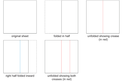
Step 1: Fold a blank sheet of paper in half from top to bottom. Then fold it in half again.
Step 2: Unfold the sheet of paper and draw lines along the creases. Then, draw a circle with a radius of at least 8 cm. The centre of the circle is the point where the lines cross.
TT 3. With your measure, check to see that the angle between the two lines is 90°. Explain why the angle must be 90° in measure.
Step 3: Write the measures of the angles as you go once around the circle, as shown in the following graphic.
Step 4: Fold the paper as before. Then fold the paper at the centre to form a triangle. The folded edges shown at the bottom of the diagram must match. Then cut off the excess paper on the right (shaded pink) so that a square is created when you unfold the paper, as shown. Draw lines along the new creases.
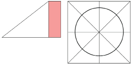
TT 4. Without using a protractor, infer how large each of the eight angles is. In your answer, explain how you can use just the positions of the creases and lines to obtain a measure for each of the angles.
TT 5. Write the measures on each of the new angles as you did in Step 3.
Step 5: Fold your paper back into the triangle of Step 4.
Now, fold the triangle from Step 4 in half, as shown in the following diagram, to form the smaller triangle.
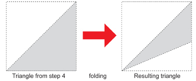
Now, unfold the paper. You should have 16 small angles formed at the centre of the paper.
TT 6. How large is each of the 16 small angles. Why?
TT 7. Write the measures on the new angles as before.
You have divided your circle into four, eight, and 16 angles, which you can use as benchmarks or referents to estimate the size of a given angle.
However, there is one more task for you to do. You will form 30-degree and 60-degree angles to also use as referents. These two angles will help to refine your estimates.
 Self-Check
Can a folding exercise be used to create the 30-degree and 60-degree referents?
If possible, work with a partner.
You will each need a square sheet of white paper, scissors, a protractor, and a compass.
Step 1: Fold the square sheet of paper in half. (See the following diagram.) Unfold the sheet. Then, fold the right half in toward the centre crease. Now, unfold the sheet to reveal the two creases.
SC 1. What fraction of the entire sheet is each narrow vertical strip composed of? Why?
Step 2: Take corner C in the next diagram and place it on the right quarter line as shown. While holding the corner on that line, crease the paper so that the crease passes through the bottom endpoint of the centre line. Cut out the triangle (shown in green).
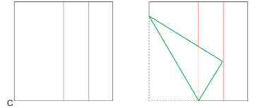
SC 2. Using your protractor, measure each angle of the triangle. How large is each angle? On each angle of the triangle, write its measure.
Sizing an Angle in the Folding
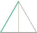
The reason one of the angles is 60° is because the small triangle in the bottom right corner is an equilateral triangle.
In any triangle the sum of the angles is 180°. In an equilateral triangle, a special triangle with three equal sides, the three angles are equal in size.
So, each of the three equal angles must be 60°. Why? Because 3 × 60° = 180°.
1.4. Page 4
Module 5: Angles
Bringing Ideas Together
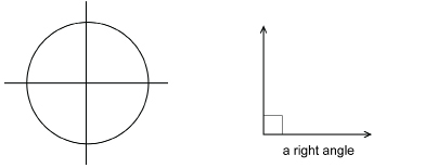
right angle: one-quarter of a complete rotation
It is 90° in measure.
acute angle: an angle greater than 0° but less than 90°
This is an acute angle.
obtuse angle: an angle greater than 90° but less than 180°
This is an obtuse angle.
straight angle: one-half of a rotation; an angle of 180°
This is a straight angle.
![]()
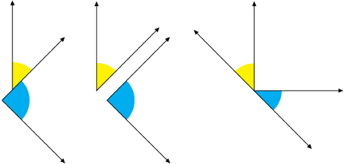
reflex angle: an angle having a measure greater than 180° but less than 360°
This is a reflex angle.
full rotation: an angle having a measure of 360°
This is a full rotation angle.
![]()
In Getting Started and Explore, you reviewed the parts of an angle, how they are measured, and what referents may be used to estimate their size. Before adding to your estimation skills, you will revisit how angles are classified by measure.
In Explore, you began by folding a sheet of paper to divide one complete rotation into quarters.
Each of the four angles was ![]() in measure.
in measure.
Most home designs involve countless right angles. Walls and floors meet at right angles—corners are square. A small square is often drawn between the arms of a right angle.
Use the applet “Acute Angle” to investigate acute angles. As you drag the movable dot to change the angle size, watch for a colour change in the text. Between what degrees is an angle considered acute? What happens if the angle is greater than 90°?
The word acute means “sharp.” Do you agree this is an appropriate name to describe what you now know as acute angles?
Use the applet “Obtuse Angle” to investigate obtuse angles. Between what degrees is an angle considered obtuse?
You should now be able to define the term obtuse angle.
Did You Know?
The word obtuse means “dull.”
Use the applet “Straight Angle” to investigate straight angles, which are a type of angle that can look like a simple straight line.
Another type of angle is a reflex angle. Use the applet “Reflex Angle” to investigate this type of angle.
Estimating Angle Measures with Referents
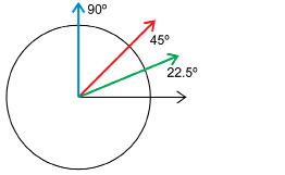
Next, you will estimate angles using the referents you discovered in Explore. You will need the circle diagram you prepared through paper folding and the triangle containing the 30° and 60° angles.
Look at your circle diagram again.
The 45° angle (red) is ![]() .
.
The 22.5° angle (green) is ![]() .
.
If you were to place 30° and 60° on the circle, those angles would divide the right angle into three parts.
The 30° angle (orange) ![]() .
.
The 60° angle (yellow) ![]() .
.
So, 30°, 60°, and 90° are also useful benchmarks or referents.
Study the following examples to hone your estimation skills. You will be working with acute, obtuse, and reflex angles. You will need a protractor to check the accuracy of the estimates.
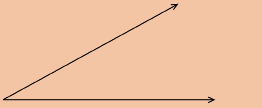
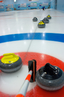
Example 1
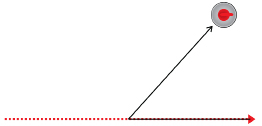
A curling stone strikes a rock in the house and is deflected from its original course.
-
State whether the angle is acute, obtuse, or reflex.
-
Estimate the angle at which the stone was deflected.
-
Measure the angle to check your estimate.
Solution
-
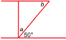
Because the angle is less than 90°, the angle is acute.
-
If a square corner from a sheet of paper is placed on the figure as shown, the angle appears to be just a little larger than of a right angle. Since
  × 90° = 45° (the referent), the angle may be 50° in measure.
-
With a protractor, the angle measures 48°.
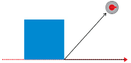
Example 2
A proton is fired from the left at the nucleus of a gold atom. The ray with the double arrow head shows the original course the electron would have taken in the absence of a collision. The electron is scattered from its original course as shown by the ray with the single arrow head.
-
State whether the angle is acute, obtuse, or reflex.
-
Estimate the scattering angle.
-
Measure the angle to check your estimate.
Solution
- The angle is greater than 90° but less than 180°, so the angle is obtuse.
If the corner of a sheet of paper is placed on the angle, it looks as though the small angle between the dashed line and the arm of the angle is about of a right angle (22.5° is the referent). So, the scattering angle is about 22.5° less than 180°. Since 180° – 22.5° = 157.5°, an estimate is 157°.
- Using a protractor, the angle measures 155°.
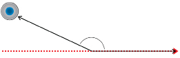
Example 3
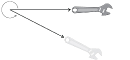
A wrench is turned counterclockwise to loosen a bolt through an angle, as shown in the following graphic.
-
State whether the angle is acute, obtuse, or reflex.
-
Estimate the angle.
-
Use a protractor to check your estimate.
Solution
-
The angle is greater than 180° but less than 360°. The angle is a reflex angle.
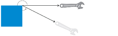
If the square corner of a sheet of paper is positioned at the vertex as shown, the small angle appears to be of a right angle (30° is the referent). So the reflex angle is about 30° less than one full rotation, 360° – 30° = 330°.
- Using a protractor, the small angle is 27°. So, the reflex angle is 333°.
 Self-Check
Do these questions. When finished, check your answers.
Use these guidelines for each angle in the questions.
- Describe the angle as acute, right, obtuse, straight, reflex, or a full rotation.
- Use a referent to estimate the measure. State the referent you used: 22.5°, 30°, 45°, or 60°.
- Use a protractor to check your estimate.
SC 3. 
SC 4. 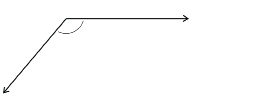
SC 5. 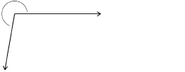
SC 6. 
 Mastering Concepts
You have seen that referents help in estimating the measure of an angle, but you can also estimate angles using a ruler.
Here is another method for estimating acute angles. You will need a ruler.
Step1: Draw any acute angle.
Step 2: From the vertex, measure out 6 cm along each arm and mark these points A and B as shown.
Step 3: Measure the distance between A and B to the nearest tenth of a centimetre.
Step 4: Multiply the distance between A and B by 10. That is the measure of the angle within a degree or two. For example, if AB = 2.3 cm, then an estimate of the angle would be 2.3 × 10 = 23°.
Step 5: Check with a protractor to see how close the estimate is.
Use these steps with several acute angles. Then, answer the following questions to see why the steps work. When finished, check your answers.
MC 1. Points A and B are 6 cm from the vertex. If you drew a circle centred at the vertex and passing through A and B, what is the circle’s approximate circumference?
MC 2. What is 10 times this circumference?
MC 3. How does the number of degrees in a circle compare to your answer in question MC 2?
1.5. Page 5
Lesson Summary
© Phillip Durand/
shutterstock
A key element of curling strategy is predicting the angles at which rocks will travel after being struck. If you have played the game, there is nothing more satisfying than seeing a well-executed shot. For fans, the satisfaction may be in seeing the side they are cheering for make a double or triple takeout.
In this lesson you explored these questions:
-
How can you sketch and describe angles of various measures?
-
How are referents used to estimate the measure of a given angle?
-
How is the protractor used to measure angles in a variety of orientations?
Check your level of understanding of the materials covered in this lesson by completing “Lesson 1 Traffic Lights.” If you select an amber or red traffic light in the multimedia piece, you will receive information about additional work you can complete to improve your understanding of the topics. Complete the suggested work before you proceed to the Lesson 1 Assignment. If you experience difficulty, contact your teacher before starting the Lesson 1 Assignment.
To answer these questions, you reviewed how protractors are used to sketch and measure angles. From their measure, you described these angles as acute, right, obtuse, straight, reflex, or a full rotation. You also explored angle referents, such as 22.5°, 30°, 45°, and 60°, to estimate the measure of any given angle.
 Assignment
Retrieve the Lesson 1 Assignment Booklet you saved in your course folder at the start of this lesson. Complete the Assignment.
Resave your Assignment Booklet in your course folder and submit a copy to your teacher for assessment.
Unit 3 Project
If angles were poorly understood, there would be no pool “sharks” or curling at the Winter Olympics. Throughout this lesson you looked at various types of angles and saw how they can be identified in many different games and hobbies. The Unit 3 Project deals with geometry found in games and hobbies.
Have you read about this project yet? Now is the time. You are at a point where you will have to give some thought to what topic you would like to work on. Let your teacher know what topic you have chosen for your Unit 3 Project.
1.6. Lesson 2
Module 5: Angles
Lesson 2: Constructing Congruent Angles
Focus
© Alice Day/shutterstock
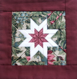
Lakota star quilts remind people that art and design play an important role in the lives of First Nations people of the prairies and plains. This design represents the Morning Star and signifies a fresh start to a person’s life. Blankets and quilts, such as the one in the photograph, are given as gifts to celebrate births, weddings, and other milestones.
The pattern incorporates the repetition of angles and geometric shapes. If you examine the star closely, you can see how carefully identical—that is, congruent—geometric figures are stitched together to create a star. In the star you can see congruent parallelograms, triangles, rectangles, and trapezoids. How many sets of congruent angles can you find?
Lesson Questions
In this lesson you will explore the following questions:
- How are congruent angles defined?
- How are congruent angles constructed?
Assessment
You will complete the Lesson 2 Assignment Booklet for assessment. Download the Lesson 2 Assignment Booklet and save it in your course folder now. You will receive instructions on how to complete the Assignment Booklet later in the lesson. You will also be prompted to start working on the Unit 3 Project.
Remember to save all activities, including those that are not part of the Assignment, in your course folder.
Required Materials and Equipment
For this lesson you will need
- a protractor
- a compass
- a square from a geometry set
- several blank sheets of paper
- a straightedge or ruler
1.7. Page 2
Module 5: Angles
Get Started
In the next activity you will examine angles found around you and learn to identify congruent angles.
 Try This
Work with a partner, if possible.
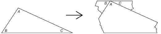
You may recall working with congruent angles in previous math courses. Do you remember what a congruent angle is? Take a look at the image of the star quilt in “What is a Congruent Angle?” Scroll over the image, and you will see a sample of congruent angles highlighted for you in the quilt. Do you remember what congruent means now?
Now, take a few minutes to look around your surroundings. Inside a building or outdoors there are many examples of congruent angles. For instance, look at where the corner of the room meets the ceiling.

At the ceiling corner there are three congruent angles. Why?
congruent angles: angles with the same measure
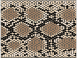
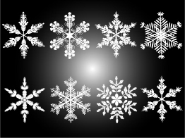
Nature’s patterns display congruent angles. Look for them on images of a snake’s skin, a butterfly’s wings, and a snowflake. Can you identify the congruent angles in these images?
© SRNR/shutterstock
© Inna Petyakina/shutterstock

© John David Bigl III/shutterstock
TT 1. Make a list of at least ten sets of congruent angles you see around you. Save your list. You will be asked for items from your list in the Lesson 2 Assignment.
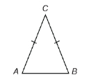
As well as in your home or in nature, you encountered congruent angles in geometric shapes you explored in previous mathematics courses. For example, suppose you were shown an isosceles triangle—a triangle with two equal sides.
You would write ![]() and would shade those angles as follows.
and would shade those angles as follows.
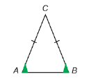
View the applet “Isosceles Triangle,” which demonstrates that the angles across from the equal sides in an isosceles triangle are congruent.
Save your answers for TT 2 through TT 5 in your course folder; you will be asked for your answers in the Lesson Assignment.
For each of the shapes in TT 2 through TT 5, first list and then shade the congruent angles in a sketch of the shape.
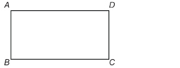
TT 2. ABCD is a rectangle.
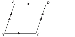
TT 3. ABCD is a parallelogram.
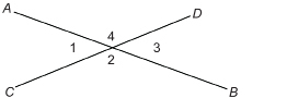
TT 4. ![]() intersects
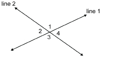
intersects ![]() , forming angles 1, 2, 3, and 4 as shown.
, forming angles 1, 2, 3, and 4 as shown.
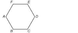
TT 5. ABCDEF is a regular hexagon—a polygon with six equal sides.
1.8. Page 3
Explore
In this activity you will construct congruent angles through paper folding.
 Try This
If possible, work with a partner. You will each need a blank sheet of paper and a straightedge or ruler.
Step 1: On the top half of a blank sheet of paper, draw an acute ∠ABC.
Step 2: Fold the sheet of paper to construct a second ∠DEF congruent to ∠ABC.
TT 6. Write out the steps you used to form ∠DEF.
TT 7. Use your protractor to measure ∠DEF and ∠ABC to check if they are congruent. Record their measures.
 Share
Share
Once you have completed the activities in Explore, share the strategy you used to produce the congruent angle DEF. Also share the proof to show that you were successful. Compare your strategy with others. Are there similarities in your approaches or differences? Summarize your strategy and include changes you might make based on viewing other students’ strategies.
Save a copy of this summary in your course folder.
1.9. Page 4
Bringing Ideas Together
In Getting Started and Explore, you examined what it means to say that two or more angles are congruent. You saw that there are congruent angles all around you—in building design, in art, and in nature. Also, in Explore, you formed congruent angles through paper folding.
straightedge: a rigid strip of wood, metal, or plastic having a straight edge used for drawing lines
When a ruler is used without reference to its measuring scale, it is considered to be a straightedge.
In the next activity you will construct congruent angles using another approach—one that geometers have used for thousands of years. You will use your compass and a straightedge to draw congruent angles. Only after you are done will you use your protractor to measure the angles to check the accuracy of your construction.
But before you begin, review how to identify angles.
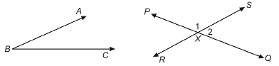
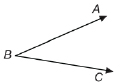
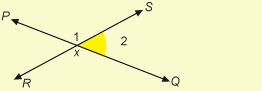
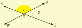
If an angle stands alone as ∠ABC does, you may use a single letter to name it. ∠ABC and ∠B are the same angle. Notice that when a three-letter name is used, the middle letter is always the vertex. Likewise, the vertex is the only letter you can use for a single-letter name.
When there are two or more angles at a point, as when ![]() intersects
intersects ![]() at point X, confusion is possible. To distinguish among the angles, you must use a three-letter name or number the angles.
at point X, confusion is possible. To distinguish among the angles, you must use a three-letter name or number the angles.
So at the intersection of the lines, ∠PXS is ∠1 and ∠QXS is ∠2.
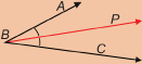
Now use your compass and a straightedge to construct an angle congruent to ∠A.
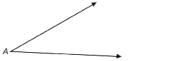
Step 1: Draw a ![]() This will be the lower arm of the new angle. Notice that it does not have to point in the same direction as the lower arm of ∠A.
This will be the lower arm of the new angle. Notice that it does not have to point in the same direction as the lower arm of ∠A.
Step 2: Use your compass to draw circles with the same radius centred at A and at B.
The first circle cuts through the arms of ∠A at P and Q. The second circle cuts across ![]() at X.
at X.

Step 3: With centre Q, draw a circle through P. With centre X and the same radius, draw a similar circle cutting the circle you drew in Step 2 at Y.
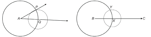
Step 4: Draw ![]() Use your protractor to check that
Use your protractor to check that ![]()
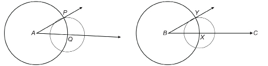
Go to the applet “Constructing Congruent Angles” to view the construction of congruent angles demonstrating a compass and straightedge construction.
 Self-Check
SC 1. Draw any obtuse angle. Then, with a compass and a straightedge, follow the steps you were just given to construct a second angle congruent to the obtuse angle. Then use a protractor to check whether your second angle is actually congruent to the first.
Stairs and Roofs
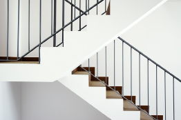
© Mrfotos/shutterstock
In construction, carpenters use their carpenter squares to measure horizontally and vertically to obtain the angle required for projects such as stairs or roofs.
Think of a set of stairs.
The angle of the stairs does not change. Can you suggest a reason why?
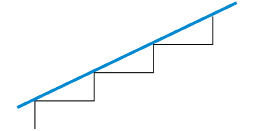
This uniformity guarantees that the angles are the same from step to step. You could lay a straight board on the steps to check. The board would rest on all the step edges.
The ratio of the riser height to the tread length affects the steepness or angle of the stairway. In other words, the vertical and horizontal measurements of a stairway affect its angle. Also for a roof, vertical and horizontal distances affect the angle of the roof.
The following is an example of how the slope of a roof can be determined from vertical and horizontal distances.
Example 1
 © Jim Parkin/Fotolia.com
Akiko and her father are building a house and an attached garage. The slope of the garage roof is a 4-in rise for every 12 in measured horizontally.
- Draw a diagram of the roof using quarter-inch grid paper.
You will need one sheet for the example and another sheet for the Self-Check.
- Measure the angle at which the roof rises.
Solution
Use one square to represent one inch.
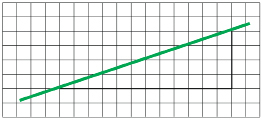
- Use your protractor to measure the angle.
The angle of the roof is approximately 18.5°.
Self-Check
SC 2. For a roof that slopes at 45°, what is the rise (in inches) for a horizontal run of 12 in?
SC 3. Use grid paper to determine the angle at which a ladder rests against a vertical wall. The foot of the ladder is 3 ft from the wall, and the top of the ladder rests against the wall 8 ft above the ground.
 Mastering Concepts
Try this question. To do this question you will need your protractor. When you are finished, check your answer.
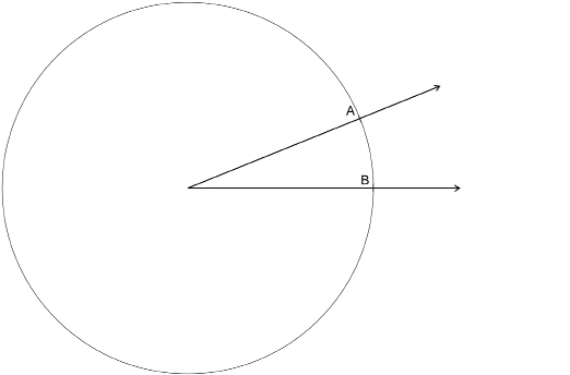
Compare the following angles.
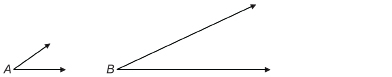
Which of the following statements best describes the relationship between ∠A and ∠B?
- ∠A is smaller than ∠B.
- ∠A is congruent to ∠B.
- ∠A is larger than ∠B.
Justify your answer.
1.10. Page 5
Module 5: Angles
Lesson Summary

© Ingvald Kaldhussater/shutterstock
The game being played in the photograph involves first folding a square sheet of paper into a shape that can be closed or opened as a name is spelled or a number is counted out. The process of folding a piece of paper into various shapes is a traditional Japanese folk art called origami. The folds create an interplay of angles and geometric shapes. Can you identify congruent angles in the figure?
In this lesson you explored the following questions:
- How are congruent angles defined?
- How are congruent angles constructed?
Check your level of understanding of the materials covered in this lesson by completing “Lesson 2 Traffic Lights.” If you select an amber or red traffic light in the multimedia piece, you will receive information about additional work you can complete to improve your understanding of the topics. Complete the suggested work before you proceed to the Lesson 2 Assignment. If you experience difficulty, contact your teacher before starting the Lesson 2 Assignment.
 Assignment
Retrieve the Lesson 2 Assignment Booklet you saved in your course folder at the start of this lesson. Complete the Assignment.
Resave your Assignment Booklet in your course folder and submit a copy to your teacher for assessment.
Unit 3 Project
Now, before you move on to Lesson 3, take a good look at the topic you chose for your Unit Project. The Unit 3 Project deals with angles.
- Where can you see angles?
- Are angles part of the board game or field lines?
- Are angles involved in the ball motion or player movements? Are angles visible in the design or in its construction?
- Are any of these angles congruent?
List areas where angles could possibly be found, and include sketches and photos where possible. Remember to save all this work, since it will be needed to complete your Unit 3 Project.
1.11. Lesson 3
Module 5: Angles
Lesson 3: Bisecting Angles
Focus
© Gizmo/iStockphoto
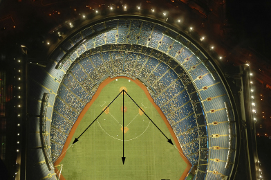
The photograph is a panoramic view of Rogers Centre, formerly called the Toronto SkyDome. Rogers Centre is the home of the Toronto Blue Jays, baseball’s World Series winners in 1992 and 1993.
If you take a closer look at the photo’s centre, you will see the layout of the baseball diamond. The first and third baselines form the angle that determines whether a ball is hit fair or foul. Second base, the pitcher’s mound, and home plate split that angle into halves. What is the measure of each half of that large angle?
In this lesson you will explore the geometry of angles and the lines that bisect, or divide, the angles into halves.
Lesson Questions
In this lesson you will explore these questions:
-
What does it mean to bisect an angle?
-
How are different techniques used to bisect angles?
Assessment
You will complete the Lesson 3 Assignment Booklet for assessment. Download the Lesson 3 Assignment Booklet and save it in your course folder now. You will receive instructions on how to complete the Assignment Booklet later in the lesson. You will also be prompted to start working on the Unit 3 Project.
Remember to save all activities, including those that are not part of the Assignment Booklet, in your course folder.
Required Materials and Equipment
For this lesson you will need the following supplies:
-
a protractor
-
compasses
-
a square from a geometry set
-
several blank sheets of paper
-
a straightedge or ruler
1.12. Page 2
Module 5: Angles
Get Started
bisect: to divide into two congruent (equal in measure) halves
bisector: a line or ray that divides a geometric shape into congruent halves
![]() is a bisector of ∠ABC, since
is a bisector of ∠ABC, since ![]() bisects ∠ABC into two congruent halves.
bisects ∠ABC into two congruent halves.
![]()
symmetry: the property of being the same size and shape on both sides of a central dividing line
Mike and Anna are discussing baseball. Anna plays baseball, and Mike has not really played, so Anna explains the game to Mike. She tells Mike that the lines running from home plate to the first and third bases form an angle. Anna explains to Mike that this angle is split into halves by the imaginary line running through second base, the pitcher’s mound, and home plate.
In the language of geometry, you could say that the ray from home base through the pitcher’s mound and second base bisects the larger angle. This ray is the bisector of the larger angle.
In their talk about baseball, Anna made Mike more aware of the bisector in a baseball diamond. Bisectors are a common feature not only in sports, but in design, nature, and art.
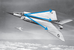
National Film Board of Canada. Photothèque/Library and Archives Canada/
PA-111546
Look at the shape of the Avro Canada CF-105 Arrow. This fighter aircraft, designed in the 1950s, was considered the most advanced aircraft of its kind! Its delta-wing design illustrates a number of bisected shapes and angles. This is an example of symmetry.

© Nguyen Thai/32618/Fotolia
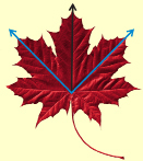
Nature provides examples of symmetry, too. For example, study the veins in a leaf. In a maple leaf, as in most other leaves, there is symmetry. One half of the leaf is the mirror image of the other half.
Can you sketch an angle and its bisector formed by the veins in the leaf?
 Try This
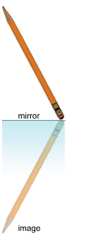
In this activity you will bisect an angle using a mirror.
Step 1: Take a pencil and place one end against a mirror. Notice that the pencil and its image form an angle, with the vertex located at the point where the pencil touches the mirror.
Step 2: Change the size of the angle between the pencil and its image, all the while keeping the end of the pencil on the mirror. Then answer the following questions.
Save your answers to TT 1 and TT 2 in your course folder. You will be prompted to copy these answers to your Assignment Booklet later in this lesson.
TT 1. Where is the bisector of the angle formed by the pencil and its reflected image located?
TT 2. How is this demonstration with the pencil related to the concept described earlier with reference to the leaf and the design of the Avro Arrow?
The angles formed by the veins are bisected by the central vein running from the stem to the top of the leaf. An angle and its bisector are drawn on the leaf.
© Nguyen Thai/32618/Fotolia
1.13. Page 3
Module 5: Angles
Explore
In this activity you will bisect an angle by folding paper. You will need a blank sheet of paper, a straightedge, and your protractor.
 Try This
Step 1: On a blank sheet of paper, draw any angle, and name the angle ABC. Measure and record the size of ∠ABC.
Step 2: Fold the sheet of paper to construct the bisector of ∠ABC. Label the bisector ![]()
Step 3: Measure and record the size of ∠ABD and ∠CBD.
TT 3. Explain how you formed the bisector of ∠ABC by folding paper.
TT 4. Give the reason why the line you labelled ![]() must be the angle bisector.
must be the angle bisector.
TT 5. State the measures of ∠ABC, ∠ABD, and ∠CBD. How are these measures related?
 Share
Share
You have now experienced one method of bisecting an angle. Share your answers with your partner or collaborate with a group. When might this technique of creating a bisector not be useful? Search the Internet for a video or lesson that shows a different method you could use to bisect an angle. Share a description of the method and the link to the video. Describe a situation where this new method might be more useful than the method you used in TT 1 to TT 5.
Save a copy of this Share in your course folder.
1.14. Page 4
Module 5: Angles
Bringing Ideas Together
In Getting Started and Explore, you examined what it means to bisect an angle. In your next activity you will construct the bisector of an angle using a classical approach—one that geometers have used for thousands of years.
You will use only your compasses and a straightedge. After you are done, you will use your protractor to check the accuracy of your construction.
View “Bisect an Angle,” which shows the technique of using a compass to bisect an angle. This is “Example Two” on the applet.
 Self-Check
Respond to these questions. When you are finished, check your answers.
SC 1. Draw any obtuse angle. Use your compasses and a straightedge to bisect the angle. Check the accuracy of your construction with your protractor.
SC 2. A student bisected a 234° angle. A protractor was used to measure each half. The student said that each half was 63°. What mistake might have been made? How large should each half have been?
Using a Carpenter’s Square to Bisect an Angle
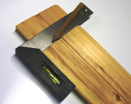
© Tom Oliveira/shutterstock
A carpenter’s square is shown in this photograph.
In construction, carpenters use carpenter squares to bisect angles. You can use one of the squares from your geometry set to bisect an angle. The following example will show the technique of bisecting an angle using a square.
Example 1
Use a square to bisect an angle.
Solution
Watch “Lesson 3: Example 1 Solution” to see how to bisect an angle.
Self-Check
Respond to this question. When you are finished, check your answer.
SC 3. Use the method shown in the example to bisect a 120° angle.
 Mastering Concepts
Try this question. When you are finished, check your answer.
Zander says he can bisect a 300° angle by bisecting the 60° angle that completes the full rotation and extends the bisector of the 60° angle in both directions. Is Zander right or wrong?
If Zander is right, explain why he is right. If Zander is wrong, explain why he is wrong.
1.15. Page 5
Module 5: Angles
Lesson Summary

© Tatiana Grozetskaya/shutterstock
Many photographs and paintings of alpine scenery involve reflections in the mirror surfaces of mountain lakes. The angles formed by the mountains and their reflections are bisected at the shoreline. This lesson involved similar relationships between the arms of angles and the bisectors of those angles. Bisectors behave like mirrors, reflecting each arm into the other.
In this lesson you explored these questions:
-
What does it mean to bisect an angle?
-
How are different techniques used to bisect angles?
Check your level of understanding of the materials covered in this lesson by completing “Lesson 3 Traffic Lights.” If you select an amber or red traffic light in the multimedia piece, you will receive information about additional work you can complete to improve your understanding of the topics. Complete the suggested work before you proceed to the Lesson 3 Assignment. If you experience difficulty, contact your teacher before starting the Lesson 3 Assignment.
You also investigated the definition and construction of angle bisectors. To construct these angles, you used paper folding, compasses and a straightedge, and squares from a geometry set.
 Assignment
Retrieve the Lesson 3 Assignment Booklet you saved in your course folder at the start of this lesson. Complete the Assignment. Resave your Assignment Booklet in your course folder and submit a copy to your teacher for assessment.
Unit 3 Project
If you are a scrapbooker or are interested in design, you have most likely needed to find the middle of an angle and have been using your bisecting skills without even realizing it. Examine your Unit 3 Project topic. Where might an understanding of bisectors be useful? Can you visualize anywhere that an angle might be bisected? Save any notes and sketches for use in your Unit 3 Project.
1.16. Lesson 4
Module 5: Angles
Lesson 4: Relationships Among Angles
Focus
© Tina Rencelj/shutterstock
Did You Know?
Soccer is the most-watched sport in the world. Soccer is called football outside of North America.
© Tina Rencelj/shutterstock
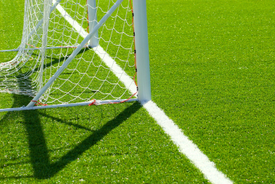
Geometry is the study of shapes and their relationships. The search for relationships is important in all branches of mathematics. In fact, seeking patterns and relationships is a strong function of the human mind! Art, architecture, games, and music all make use of patterns.
Shapes, patterns, and relationships are all around you. For example, look at the interplay between the light and shadows by the goal on the pictured soccer pitch. You will see triangles, trapezoids, parallelograms, and a variety of angles. You will even see patterns on the grass!
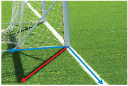
The shadow of the goalpost nearest you divides a right angle into two acute angles, as you can see in the second image. What terms describe this angle pair?
Lesson Questions
In this lesson you will explore these questions:
- What are complementary and supplementary angles?
- What are vertically opposite angles?
- How are complementary and supplementary angles used to solve problems?
Assessment
You will complete the Lesson 4 Assignment Booklet for assessment. Download the Lesson 4 Assignment Booklet and save it in your course folder now. You will receive instructions on how to complete the Assignment Booklet later in the lesson. You will also be prompted to start working on the Unit 3 Project.
Remember to save all activities, including those that are not part of the Assignment, in your course folder.
Required Materials and Equipment
For this lesson you will need the following supplies:
- a protractor
- tape
- scissors
- several blank sheets of paper
- a straightedge or ruler
1.17. Page 2
Module 5: Angles
Get Started
In this activity you will review several angle relationships that you examined in previous math courses.
 Try This
Work with a partner, if possible.
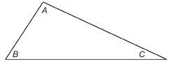
Step 1: On a blank sheet of paper, draw a triangle of any shape and size. Label the angles as shown, and measure the angles with a protractor. Record these measures.
Step 2: Cut out the triangle, and then tear off ∠B and ∠C.
Step 3: Place ∠B and ∠C next to ∠A so that all three vertices lie at the same point.
Notice that the three angles at A form a straight line. Do you remember that the measure of a straight angle is 180°?
 Self-Check
SC 1. Calculate ∠A + ∠B + ∠C. Will this sum be the same for any triangle you draw? Why?
Next, you will apply this relationship among the angles of a triangle.
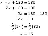
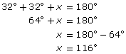
Example 1
Find the missing measure of ∠A.
Solution
In a triangle, all the angles add up to 180°, so you know that the following is true: ∠A + ∠B + ∠C = 180°. Use this information to find the value of ∠A.
Then check your answer.
![]()
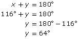
Self-Check
SC 2. Find the missing measure. When finished, check your answer.
1.18. Page 3
Module 5: Angles
Explore
In the Get Started section you reviewed the angle relationships based on the three angles of a triangle. There are also angle pairs that have special relationships. Having words to describe angle pairs will be of help in discovering angle relationships.
The coloured angles are adjacent angles.
 Self-Check
SC 3. This illustration shows three pairs of angles.
Explain why all of these pairs are not adjacent pairs.
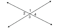
Intersecting Lines
The sizes of adjacent angles at the intersection of two lines are connected in a special way.

Can you identify pairs of adjacent angles at the intersection of line 1 and line 2?
![]() Self-Check
Self-Check
SC 4. Using the diagram in Intersecting Lines, complete the following statement. Then justify your answer.
∠1 + ∠2 = ____°.
SC 5. What is the sum of the measures of a pair of adjacent angles formed by intersecting lines?
supplementary angles: two angles that add up to 180°
In a pair of supplementary angles, one angle is the supplement of the other.
In the diagram you’ve been considering, ∠1 and ∠2, a pair of adjacent angles, are supplementary angles. Not all supplementary angles are adjacent. This is demonstrated in the following question.
Self-Check
SC 6. In the following angle pairs, ∠c has a measure of 60°, and ∠d has a measure of 120°.
Which of these angles are supplementary angles but not adjacent angles?
Around the Corner
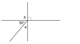
You saw that the angles at the intersection of two lines were connected in a special way. There is also a special connection between the sizes of adjacent angles making up a right angle.
Look at ∠a and ∠b in the following diagrams.
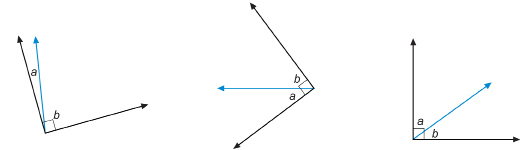
SC 7. Complete the following statement. Then justify your answer.
∠a + ∠b = ____°.
complementary angles: two angles with measures that add up to 90°
One angle is called the complement of the other.
∠a and ∠b are not only adjacent angles; they are also complementary angles. But not all complementary angles are adjacent. This is demonstrated in the following question.
Self-Check
SC 8. In the following diagram, ∠c has a measure of 60° and ∠d has a measure of 30°.
Which of the angles shown are complementary angles but not adjacent angles?
Angle Pairs in Your World
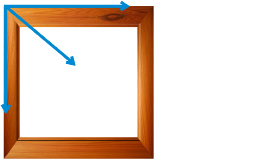
Complementary angles often occur at right-angle corners. For example, look at the square corners of a picture frame. The pieces that form the frame are cut at angles that add up to 90°. Commonly, those complementary angles are each 45°, but they don’t have to be equal. One could be 40° and the other could be 50°.
© YuM/shutterstock
There are countless examples of adjacent angles in nature, construction, art, and architecture.
What type of angle pairs are found in each of the following pictures?
© Martin Maun/shutterstock
 © John Leung/shutterstock
© Jim Parkin/4071317/Fotolia
 Share
Share
In Lesson 2 you identified angles in the topic for your Unit 3 Project. Now is a perfect time to find an example of a supplementary or adjacent angle pair. Use a sketch or photo to illustrate one of these angle pairs from your topic. Share these images with others and see what they have done—this might help you with your own project.
Save a copy of your work in your course folder as you will need this information for your Unit 3 Project.
1.19. Page 4
Module 5: Angles
Bringing Ideas Together
You worked with the angles in a triangle. You demonstrated that the sum of the angles is 180° by showing that these angles can be arranged to form a straight angle. You have also demonstrated that any pair of adjacent angles formed at the intersection of lines adds up to 180°. There is another angle relationship that is based on 180° and involves intersecting lines.
vertically opposite angles: angles lying across from each other at the point where two lines intersect
Vertically opposite angles are also referred to as opposite angles.
Line 1 and line 2 intersect to form two pairs of angles called vertically opposite angles or, simply, opposite angles. In the diagram, ∠1 and ∠3 are vertically opposite angles. Also, ∠2 and ∠4 are vertically opposite angles.
 Try This
In this activity you will explore how vertically opposite angles are related.
On the applet “Opposite Angles,” change the position of lines 1 and 2 to change the way the lines intersect.
Based on your investigation of vertically opposite angles in “Opposite Angles,” what conclusion could you make about the angles’ measures?
Answer the following questions to show, mathematically, how the sizes of the vertically opposite angles compare.
 Self-Check
First, you will show that ∠1 is congruent to ∠3.
SC 9. Complete the following statement. Then justify your answer.
∠1 + ∠2 = ____°.
SC 10. Complete the following statement. Then justify your answer.
∠3 + ∠2 = ____°.
SC 11. Using the results from SC 9 and SC 10, show (in a mathematical way) why ∠1 + ∠2 = ∠3 + ∠2.
SC 12. Use a similar approach to show that ∠2 is congruent to ∠4.
Try This
TT 1. Next, you will demonstrate that opposite angles are congruent by folding paper.
Step 1: Draw a pair of intersecting lines on a blank sheet of paper. Label the opposite angles as shown.
Step 2: Use your protractor to measure the opposite angles. What do you notice?
Step 3: Explain how to fold your sheet of paper to demonstrate that the opposite angles are congruent.
Using Angle Relationships
In the following examples and practice questions, you will apply the angle relationships you examined. These angle relationships will include the following angles in a triangle:
- vertically opposite
- adjacent
- complementary
- supplementary
Example 2
A student studying geometry in architecture used the following picture to illustrate the angles made by the roof of a structure.
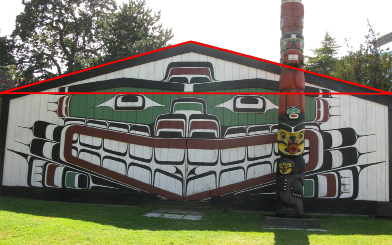
© David Strand
The angle at the top of the roof was measured to be 150°. The two angles at the base are equal. What is the measure of each angle?
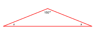
Solution
The sum of the measures of the three angles of the triangle is 180°. Therefore,
Check
![]()
Each angle at the base is 15°.
Sum of the Angles of a Triangle
Remember that when you rip off the corners of any triangle, you will see they form a line and add up to 180°.
Example 3
The W-type roof truss is the most common type of truss in simple wood-frame construction.
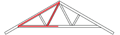
The angles will depend on the roof’s pitch. If the pitch of the roof is 32°, calculate the values of x and y.
Solution
First, find the value of x.
The sum of the angles in the triangle is 180°.
The angles with measures x and y are supplementary.
Example 4
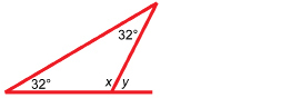
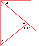
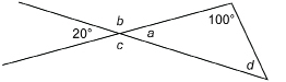
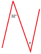
Two straight paths cross at 30° as shown. Find the measures of the other three angles, which are represented by a, b, and c.
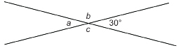
Solution
The angle with measure a is opposite the 30° angle. Therefore, a = 30°.
The angles with measures a and b are supplementary. So,
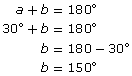
The angle with measure c is opposite b.
Therefore, c = b = 150°.
Example 5
Angles A and B are angles of a right triangle.
Show that ∠A and ∠C are complementary.
Solution
Watch “Lesson 4: Example 5 Solution.”
Self-Check
Respond to the following questions.
SC 13.
- Name two pairs of complementary angles.
- Name one pair of supplementary angles.
SC 14. Calculate the angle measures of a and b.
SC 15. Find the angle measures of a, b, c, and d for the rectangular envelope shown in the photograph. In the figure, ∠b = ∠c.

© mayamaya/shutterstock
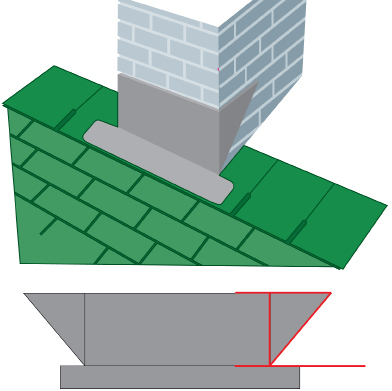
SC 16. The layout for a sheet-metal front-cap flashing to be positioned at the front of a chimney is shown. Find the missing measures a and b.
SC 17. Find the indicated measures.
 Mastering Concepts
Try this question. When you are finished, check your answer.
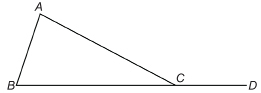
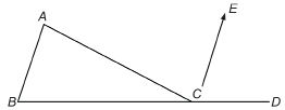
The angles within a triangle are called interior angles. If a side of a triangle is extended, an exterior angle is formed.
In ΔABC, ∠A, ∠B, and ∠ACB are interior angles. ∠ACD is an example of an exterior angle.
Show that the following is true: ∠A + ∠B = ∠ACD.
1.20. Page 5
Module 5: Angles
Lesson Summary
© Canadian Museum of Civilization, no. III-X-290 a-b, D2005-05016
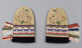
The mittens in the photograph are part of the Canadian Museum of Civilization’s collection of art and artifacts. The mittens were made by a Cree artisan. The artisan created an imaginative geometric design using triangles. Angles in triangles are just one of the angle relationships you examined in this lesson.
In this lesson, you explored these questions:
- What are complementary and supplementary angles?
- What are vertically opposite angles?
- How are complementary and supplementary angles used to solve problems?
Check your level of understanding of the materials covered in this lesson by completing “Lesson 4 Traffic Lights.” If you select an amber or red traffic light in the multimedia piece, you will receive information about additional work you can complete to improve your understanding of the topics. Complete the suggested work before you proceed to the Lesson 4 Assignment. If you experience difficulty, contact your teacher before starting the Lesson 4 Assignment.
To answer the questions regarding complementary and supplementary angles, you examined the relationships among adjacent angles, angles in triangles, and angles formed by intersecting lines.
 Assignment
Retrieve the Lesson 4 Assignment Booklet you saved in your course folder at the start of this lesson. Complete the Assignment Booklet. Resave your Assignment Booklet in your course folder and submit a copy to your teacher for assessment.
Unit 3 Project
Before you move on to the next lesson, make sure you have completed and saved the images of supplementary and complementary angles you found in your topic for the Share section.
Remember to save all this work, since your work will be needed to complete your Unit 3 Project.
1.21. Lesson 5
Module 5: Angles
Lesson 5: Parallel and Perpendicular Lines
Focus
Canadian football originated in Montréal in 1865 and was then similar to rugby. Over the last 150 years, football has evolved into the game that has become, for many, a national pastime! Which is your favourite Canadian Football League (CFL) team—the Saskatchewan Roughriders, the BC Lions, or maybe the Montréal Alouettes? Or maybe another team?
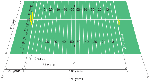
The football field in the illustration is the league’s standard. The field is 110 yd long and 65 yd wide, and the end zones are 20 yd deep. The yard lines, marked as a series of lines 5 yd apart, are all parallel to each other. Each of those yard lines is also perpendicular—that is, at 90°—to the sidelines. You probably noticed a series of hash marks set in 24 yards from the sidelines and perpendicular to the white yard lines. Do the two sets of hash marks run parallel to each other? How do you know?
Lesson Questions
In this lesson you will explore these questions:
-
How are parallel and perpendicular lines identified?
-
How can the relationship among angles formed when a line intersects parallel lines be used to solve problems?
Assessment
You will complete the Lesson 5 Assignment Booklet for assessment. Download the Lesson 5 Assignment Booklet and save it in your course folder now. You will receive instructions on how to complete the Assignment Booklet later in the lesson. You will alsobe prompted to start working on the Unit 3 Project.
Remember to save all activities, including those that are not part of the Assignment, in your course folder.
Required Materials and Equipment
For this lesson you will need the following supplies:
-
a protractor
-
scissors
-
several blank sheets of paper
-
a straight edge or ruler
1.22. Page 2
Module 5: Angles
Get Started
In this activity you will identify parallel and perpendicular lines in your surroundings, and you will justify your selection.
You will also review definitions, terms, and symbols associated with parallel and perpendicular lines.
 Try This
iStockphoto/Thinkstock
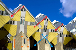
Work with a partner, if possible. Look at the modern housing units in the following image. Notice the coloured lines drawn over features of the houses. The parallel and perpendicular features are due to the design of the housing units. The blue lines are samples of perpendicular lines, while the red and orange lines are parallel. Can you see more samples of parallel and perpendicular lines in the design?
TT 1. Parallel and perpendicular lines are all around you, as you can see by looking at the photograph of the housing units. Look for some parallel and perpendicular lines in your surroundings. This list shows a few possibilities:
-
edges of a picture frame
-
corners of a room
-
lines on rule paper
-
edges of a ruler
-
tracks left by a car tire
-
railroad tracks and ties
What other parallel and perpendicular lines can you find?
TT 2. Using what you learned in TT 1, write a definition for parallel and perpendicular lines that could be used to sort lines.
Use the two demonstration applets “Parallel Lines” and “Perpendicular Lines” to further study parallel and perpendicular lines. If you need a guide for these applets, review “Help with Parallel Lines” and “Help with Perpendicular Lines.”
TT 3. After using the applets to study lines, revise your definition for parallel lines and perpendicular lines, if necessary.
Save a copy in your course folder.
Using Symbols to Describe Lines
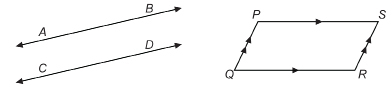
The symbol is ![]() used for “is parallel to.” In the most recent figure,
used for “is parallel to.” In the most recent figure, ![]() is parallel to
is parallel to ![]() You may write
You may write ![]() .
.
Note the symbol ![]() means “line.”
means “line.”
In the parallelogram, PQRS, ![]() . This time the symbol
. This time the symbol ![]() means “line segment”—a part of a line with definite endpoints.
means “line segment”—a part of a line with definite endpoints.
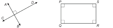
In the diagram, ![]() is perpendicular to
is perpendicular to ![]() The symbol
The symbol ![]() means “is perpendicular to.” You could write
means “is perpendicular to.” You could write ![]() .
.
In the rectangle, PQRS, ![]() .
.
Try This
Parallel and perpendicular lines can be a little less obvious in cases from the natural world.

© Oleg Golovnev/shutterstock

© Shebeko/shutterstock
If you have a magnifying glass, the geometry in the following case will be a little easier to see.
Shake a few grains of salt on a dark background. What shape is each grain?
Crystals display one case of geometry in the natural world.
Use your definition of parallel and perpendicular lines from TT 3 to answer the following questions.
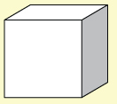
TT 4. How many parallel lines are there in a cube? Explain your answer.
TT 5. Where do perpendicular lines occur? How many perpendicular lines are there at those locations?
Save your answers to TT 4 and TT 5 in your course folder. You will be asked to include your answers in the lesson assignment.
Did You Know?
You can grow your own salt crystals quite easily.
The procedure is described in “Grow Your Own Salt Crystals.”
TT 6. Besides crystals, where else in nature can you find parallel and perpendicular lines? Make a list of at least five examples. Support your list with sketches.
In your course folder, save your answer for the lesson assignment.
Every grain of salt is a cube. Enlarged, the salt grain would look much like the following cube.
1.23. Page 3
Module 5: Angles
Explore
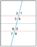
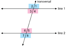
In this activity you will explore the relationships among angles formed when two parallel lines are intersected by a third line.
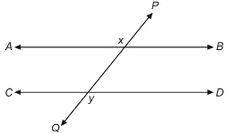
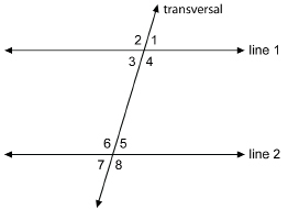
In the diagram ![]() intersects the parallel lines at points x and y. The goal of this activity is to determine relationships among the angles formed at x and y.
intersects the parallel lines at points x and y. The goal of this activity is to determine relationships among the angles formed at x and y.
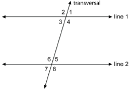
The intersecting line is called a transversal.
 Self-Check
SC 1. Look at the following diagram that shows a red line, a blue line, and a green line.
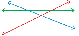
Which line or lines are transversals?
 Try This
In this activity you will explore angles formed by a transversal. Share your work from this activity and place the information in your course folder. Work with a partner if possible.
Step 1: Take a blank sheet of paper and fold it twice to form two parallel creases when unfolded.
Self-Check
SC 2. Explain how you folded the paper and why, when unfolded, the creases are parallel.
Step 2: Fold the paper again but, this time, fold the paper vertically instead of horizontally. When unfolded, the crease
will cross both parallel creases. With the aid of a ruler, draw lines on the creases. Number the angles as shown in the
diagram.

Step 3: Cut the sheet in two between the two sets of angles. One possible cut is the dashed line in the diagram.
Step 4: Cut out the four angles—∠5, ∠6, ∠7, and ∠8—by cutting along the two intersecting lines that form the angles.

Step 5: Take ∠5 and compare the angle by placing it on each of ∠1, ∠2, ∠3, and ∠4. Are any of those angles congruent (the same measure) to ∠5? If there are congruent angles, list them in the following table.
Step 6. Repeat Step 5 for ∠6, ∠7, and ∠8.
TT 7. Complete a table like the following for Steps 5 and 6.
|
Angle |
Congruent Angles from ∠1, ∠2, ∠3, and ∠4 |
|
∠5 |
|
|
∠6 |
|
|
∠7 |
|
|
∠8 |
|
TT 8. If all congruent angles are shaded the same colour, how many different colours would you need for this diagram? Explain your answer.
 Share
Share
How many colours would you need in TT 8? Make a visual representation by folding a new piece of paper or by drawing a new representation using a computer. Colour in all the angles that are congruent to each other with the same colour. Use as many colours as are necessary. How many colours did you need? Share your diagram or a photo of your diagram with your partner or group. How do your drawings compare?
Save a record of your discussion and your answers to TT 6, TT 7, and TT 8. Place your work in your course folder.
1.24. Page 4
Module 5: Angles
Bringing Ideas Together
In the Explore section you compared the angles formed when two parallel lines are cut by a transversal. You should have discovered that vertically opposite angles are congruent.
In the diagram the vertically opposite angles are ∠1 and ∠3, ∠2 and ∠4, ∠5 and ∠7, and ∠6 and ∠8.
In TT 6 to TT 8 you compared the angles formed when two parallel lines are cut by a transversal. You discovered that angles in the same corresponding positions at the two points of intersection are congruent.
In the diagram, the corresponding angles are ∠1 and ∠5, ∠2 and ∠6, ∠3 and ∠7, and ∠4 and ∠8.
The applet “Corresponding Angles” highlights these angle relationships. Move the lines around by dragging the black dots on the line. Notice how the corresponding angles remain congruent.
Investigate the following questions as you explore “Corresponding Angles.”
-
How many different angle measures are there?
-
How does this number compare with the colouring diagram you did in the Share activity?
Now rotate the lines by dragging anywhere on the line except on the black dot. Watch for the answer to this question: Do the corresponding angles remain constant?
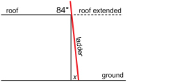
Example 1
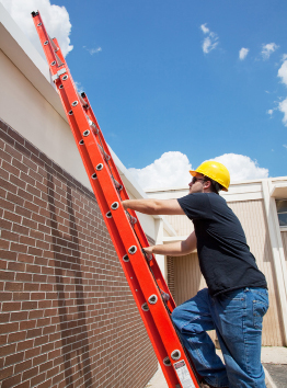
© Lisa F. Young/shutterstock
A ladder on level ground is propped against the side of a building with a flat roof (the roof is parallel to the ground). The angle between the ladder and the roof is 84°. What is the measure, x, of the angle between the foot of the ladder and the ground?
View the animated “Lesson 5: Example 1 Solution.”
Example 2
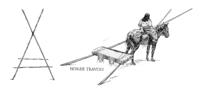
Jefferys, C. W. The Picture Gallery of Canadian History. Toronto: Ryerson Press, 1942. p 34. (left) Sparrow Illustration
Travois were used by people—like the Nehiyawak and the Siksika—on the plains and prairies to transport goods. Before the Spanish introduced the horse to North America, dogs were used to pull travois. A travois consisted of two poles lashed together and stabilized by one or more poles crossing the first two.
The following diagram matches the design of a travois.
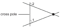
Classify ∠1 and ∠2. Are they congruent? Why or why not?
Solution
∠1 and ∠2 are corresponding angles because they lie in the same relative position at the cross pole.
They are not congruent because the other two poles (lines) are not parallel, as ∠1 is acute and ∠2 is obtuse.
Other Angles at the Transversal

In the Explore section you discovered that corresponding angles were not the only congruent pairs.
interior angles: angles lying between two lines cut by a transversal
exterior angles: angles outside two lines cut by a transversal
Look at the four angles between the parallel lines. ∠3, ∠4, ∠5, and ∠6 are interior angles.
The other four angles, ∠1, ∠2, ∠7 ,and ∠8, are exterior angles.
 Self-Check
SC 3. In the preceding diagram, which interior angles are congruent?
∠3 and ∠5 are alternate interior angles. ∠4 and ∠6 are also alternate interior angles, because they lie on alternate sides of the transversal.
Use the applet “Alternate Angles (of a Transversal)” to describe the relationship between alternate angles.
From the applet you can draw the following conclusions:
-
When two parallel lines are cut by a transversal, the alternate interior angles are congruent (equal in measure).
-
When two parallel lines are cut by a transversal, the alternate exterior angles are congruent (equal in measure).
So, in the diagram, if the lines are parallel, the alternate exterior angles are congruent. The angles coloured pink are alternate exterior angles, so ![]() . Also, the angles coloured blue are alternate exterior angles, thus
. Also, the angles coloured blue are alternate exterior angles, thus ![]() .
.
Study these examples.
Example 3
© Paul.J.West/shutterstock
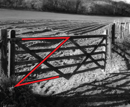
A wooden gate is crossbraced as shown. If the horizontal boards are parallel, determine the measure of the angle between one of the braces and the top horizontal board.
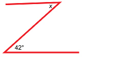
Solution
The two angles in the outline of the boards are alternate interior angles. The diagonal crossbrace is a transversal cutting across the parallel lines of the horizontal boards.
So, x = 42°.
Example 4
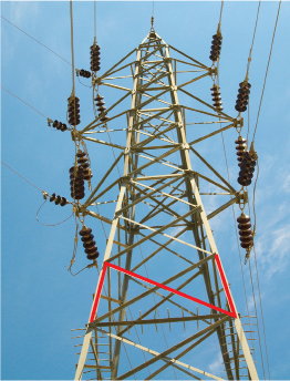
© Gulei Ivan/shutterstock
Classify the two angles in the diagram formed by the sides of the transmission tower and one of the diagonal braces. Do you have enough information to determine the value of x? Why or why not?
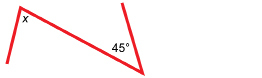
Solution
The angles in the outline are alternate interior angles. However, the sides of the tower are not parallel, so there is not enough information to find the value of x.
Another Angle Relationship
There is one more angle relationship that can be determined from the intersection of parallel lines by a transversal.
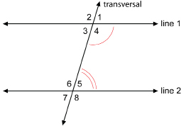
Consider the angle pair ∠4 and ∠5. What is the relationship between these two angles? The angles are not congruent, but a relationship does exist. Can you see it?
Use the applet “Transversal Angles” to help determine the relationship.
From the applet, you should have discovered that ∠4 and ∠5 are co-interior angles and are supplementary (add up to 180°). Consider this explanation as to why this is true.
The adjacent angles ∠1 and ∠4 form a straight angle—they are supplementary. So, ∠1 + ∠4 = 180°.
But ∠1 = ∠5, since they are corresponding angles. Therefore, you can substitute ∠5 for ∠1. So, ∠5 + ∠4 = 180°.
These two co-interior angles are supplementary. Similarly, the co-interior angles ∠3 and ∠6 are supplementary. So, ∠3 + ∠6 = 180°.
You may have noticed in the applet that co-exterior angles are supplementary if the lines are parallel.
![]()
Note: All of the angle relationships are reversible. If the corresponding angles are congruent, the lines are parallel. If the alternate interior or alternate exterior angles are equal, the lines are parallel. If the co-interior or co-exterior angles are supplementary, the lines are parallel.
Work through the following examples before you practise your skills.
Example 5
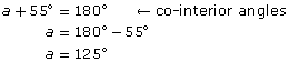
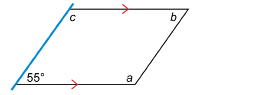
A cardboard box is partially flattened into a parallelogram, as shown in the diagram.
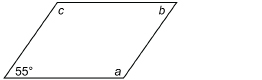
The angle at the lower left is 55°. Find the measures of the other three angles.
Solution
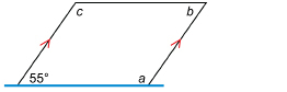
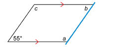
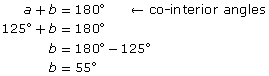
Example 6
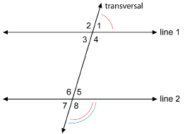
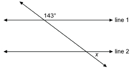
Are line 1 and line 2 parallel? Why or why not?
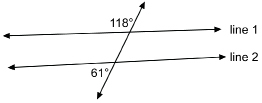
Solution
The given angles are co-exterior angles. If the lines were parallel, the co-exterior angles would be supplementary (add up to 180°).
Since 118° + 61° = 179°, line 1 and line 2 are not parallel.
Your turn!
Self-Check
Complete the following questions.
SC 4. Play “Grocery Store Game (Exploring Parallel Lines).”
Try to collect at least 14 tokens. Select [Hints] if you need to review the meaning of vertically opposite, corresponding, and alternate angles. Consider a second game if you have trouble remembering the difference between vertically opposite, corresponding, and alternate angles.
SC 5. The following figure was found as a pattern in a painting.
Based on the figure, answer the following questions:
-
Is
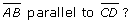 Justify your answer.
-
Calculate the value of x. State the angle property you used to justify your answer.
SC 6. This illustration shows a pair of vertical bridge supports and a crossbeam running from the top of one support to the base of the other. The angle between the second support and the beam is labelled x.
© basel101658/shutterstock
Calculate the value of x. Justify your answer. Assume the vertical bridge supports are parallel.
SC 7. Line 1 is parallel to Line 2.
Find the value of x.
 Mastering Concepts
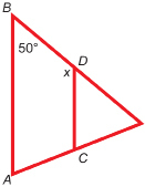
Try this question. When you are finished, check your answer.
The angles within a triangle are called interior angles. If a side of a triangle is extended, an exterior angle is formed. In DABC, ∠A, ∠B, and ∠ACB are interior angles. ∠ACD is an example of an exterior angle.
![]() Use parallel line relationships.
Use parallel line relationships.
1.25. Page 5
Module 5: Angles
Lesson Summary
© Roman Sigaev/shutterstock
In art, a sense of depth or perspective is created by drawing distant objects smaller. Parallel lines appear to converge. When you look at the picture of a perspective drawing, you have the impression that you are looking through a window. This technique is also used in architectural drawings, so that the client is given a mental image of what the building will look like when it is complete.
In this lesson you explored angles arising from this perspective—the intersection of parallel lines.
You have explored these questions:
- How are parallel and perpendicular lines identified?
-
How can the relationship among angles, formed when a line intersects parallel lines, be used to solve problems?
Check your level of understanding of the materials covered in this lesson by completing “Lesson 5 Traffic Lights.” If you select an amber or red traffic light in the multimedia piece, you will receive information about additional work you can complete to improve your understanding of the topics. Complete the suggested work before you proceed to the Lesson 5 Assignment. If you experience difficulty, contact your teacher before starting the Lesson 5 Assignment.
You discovered that when two parallel lines are intersected by a transversal, corresponding angles, alternate interior angles, and alternate exterior angles are congruent. You also discovered that co-interior angles and co-exterior angles are supplementary. As well, if these relationships in a specific instance do not hold, then the lines simply are not parallel.
 Assignment
Retrieve the Lesson 5 Assignment Booklet you saved in your course folder at the start of this lesson. Complete the Assignment. Resave your Assignment Booklet in your course folder and submit a copy to your teacher for assessment.
Explore your topic for the Unit 3 Project. Can you see parallel and perpendicular lines? Can you find places where a transversal might cross two parallel lines? Use your imagination and think of all the possibilities. Keep all your work in your course folder to help with the presentation of your Unit 3 Project.
1.26. Lesson 6
Module 5: Angles
Lesson 6: Problems Involving Parallel and Perpendicular Lines
Focus
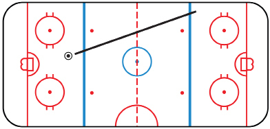
Hockey rinks are a common feature on the Canadian landscape, but have you ever looked carefully at the markings on the ice? The layout consists of a series of circles, parallel lines, and perpendicular lines.
In the illustration, a puck has travelled from the left side of the rink crossing both blue lines. The linesman’s whistle blows and the signal for “offside” is given. If the puck travelled in a straight line, what can you say about the angles at the two lines where the puck crossed?
Lesson Questions
In this lesson you will explore this question: How are the measures of angles determined in situations involving parallel lines and transversals?
Assessment
You will complete the Lesson 6 Assignment Booklet for assessment. Download the Lesson 6 Assignment Booklet and save it in your course folder now. You will receive instructions on how to complete the Assignment Booklet later in the lesson. You will also be prompted to start working on the Unit 3 Project.
Remember to save all activities, including those that are not part of the Assignment, in your course folder.
Required Materials and Equipment
For this lesson you will need the following supplies:
-
a protractor
-
scissors
-
two blank sheets of paper
-
a straightedge or ruler
1.27. Page 2
Module 5: Angles
Get Started
In this activity you will review the definitions of angles formed when two lines are intersected by a transversal.
 Try This
Work with a partner, if possible.
Use the explore feature in “Exploring Parallel Lines—Explore It” to review the positions of each of the following angle pairs:
-
vertically opposite angles
-
corresponding angles
-
alternate angles
Select each of the angles A through H in turn. Use the animation slider to explore the position of the various pairs of angles.
Now check your understanding of angle pairs reviewed in “Exploring Parallel Lines—Explore It” by completing the following Self-Check questions.
 Self-Check
Use this diagram to answer the following questions.
SC 1. Name the pairs of vertically opposite angles.
SC 2. Name the pairs of corresponding angles.
SC 3. Name the pairs of alternate interior angles.
SC 4. Name the pairs of alternate exterior angles.
SC 5. If line 1 is parallel to line 2, what can be said about each angle pair you named in your responses from SC 1 to SC 4?
If you need further review, go back to “Exploring Parallel Lines—Explore It.” Click on “use it” for a more complete review of these different angles.
1.28. Page 3
Module 5: Angles
Explore
In this activity you will review the relationships between co-interior and co-exterior angles formed when two parallel lines are intersected by a third line.
 Try This
Step 1: Draw a line on a blank sheet of paper. This line will serve as the transversal.
Step 2: On a second sheet of paper, draw a pair of adjacent supplementary angles similar to the angles shown here.
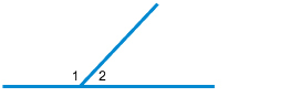
Do you remember why ∠1 and ∠2 are supplementary?
Step 3: Cut out ∠1 and ∠2 along the arms of the angles as shown.
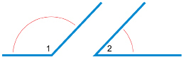
Step 4: Position the angles along one side of the transversal, so that each angle has an arm that touches the transversal and the other two arms of the angles are parallel.
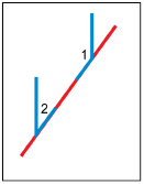
 Self-Check
SC 6. How many different ways can you arrange the angles you cut out to form parallel lines? Draw a diagram for each arrangement. For each arrangement, use the correct term you encountered in the previous lesson to describe each angle pair. For example, to describe the angle pair shown in Step 4, you could use the term co-interior.
1.29. Page 4
Module 5: Angles
Bringing Ideas Together
 Try This
In this multimedia piece you will explore the relationship between the sum of co-interior angles and the sum of co-exterior angles for parallel and non-parallel lines. As you explore this relationship between the sums, think about the following question.
Does the relationship between pairs of co-interior angles or pairs of co-exterior angles depend on the way the parallel lines are positioned on the plane?
TT 1. Go to “Exploring Parallel Lines—Explore It.” Click on “Explore It 2,” (in the middle of your screen), and follow the directions to complete the table that follows in this lesson.
Step 1: To begin, choose any transversal with parallel lines.
Step 2: Add the co-interior angles together, and record the sum in the table.
Step 3: Add the co-exterior angles together, and record the sum in the table.
Step 4: Repeat Steps 1 to 3 using parallel and non-parallel lines to fill in the table.
|
Sum of Co-Interior Angles |
Sum of Co-Exterior Angles |
|
|
Parallel Lines |
|
|
|
Example 1 |
|
|
|
Example 2 |
|
|
|
Non-Parallel Lines |
|
|
|
Example 1 |
|
|
|
Example 2 |
|
|
 Share
Share
You used “Exploring Parallel Lines—Explore It” to explore co-interior and co-exterior angles. You looked at both parallel and non-parallel lines. Share your results from TT 1 with a partner or a group, and then discuss the following question.
How does the way parallel or non-parallel lines are positioned on a plane affect the relationship between pairs of co-interior or co-exterior angles?
Write a one-sentence response to the discussion question. Save a copy of your response in your course folder.
In the Explore section of this lesson, you formed parallel lines by positioning supplementary angles along one side of a transversal. Then, in the Try This section, you saw that it does not matter which way the parallel lines are pointed on a plane. As long as the lines are parallel, the co-interior or co-exterior pairs add up to 180°.
These important relationships are summarized in the following information, and the relationships will be important as you solve problems later in this lesson.
|
One of the co-interior pairs is ∠4 and ∠5. If those two angles add up to 180°, line 1 will be parallel to line 2.
Or, vice versa, if lines 1 and 2 are parallel, that makes ∠4 and ∠5 supplementary (the angles add up to 180°).
This is also true for the other pair of co-interior angles, ∠3 and ∠6. |
|
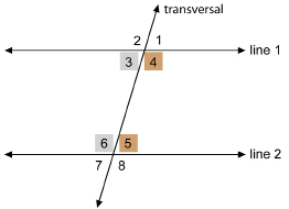
|
One of the co-exterior pairs is ∠1 and ∠8. If those two angles add up to 180°, line 1 will be parallel to line 2.
Or, vice versa, if lines 1 and 2 are parallel, then ∠1 and ∠8 will be supplementary (the angles add up to 180°).
This is also true for the other pair of co-exterior angles, ∠2 and ∠7. |
|
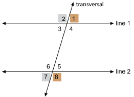
Two Lines and a Transversal
Examples 1 to 3 involve angle relationships for the following types of angles formed when two lines are cut by a transversal:
-
vertically opposite
-
supplementary
-
corresponding
-
alternate interior
-
alternate exterior
-
co-interior
-
co-exterior
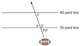
Example 1
A forward pass in football crosses the 35- and 40-yard lines as shown.
Determine the measure of angles a, b, and c. State the relationship you used to find each measure.
Solution
View the animated “Lesson 6: Example 1 Solution.”
Example 2
The outline of a kite is shown. Are the two edges drawn in red parallel? Justify your answer.
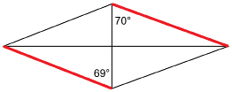
Solution
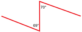
The 69° and 70° angles are alternate interior angles formed by the vertical transversal. As these angles are not congruent, the two red edges are not parallel.
Example 3
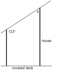
A covered deck is attached to the side of a house. Find the angle with measure a.
Solution
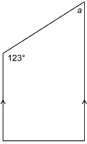
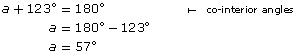
It is now your turn!
Self-Check
Complete the following questions.
SC 7.
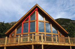
© Mark Stout Photography/shutterstock
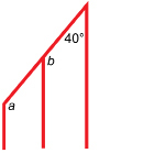
This illustration shows the measures of the angles in the overlay to the A-frame chalet’s windows. Find the missing measures for the windows of the chalet.
SC 8.
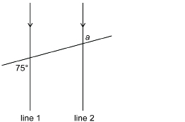
If line 1 is parallel to line 2, find a. What angle relationship did you use?
SC 9. Find the measure of ∠B.
SC 10. ![]()
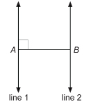
 Mastering Concepts
Try this problem. When you are finished, check your answer.
A line through point A is drawn parallel to the base of ![]() Without using a protractor, justify that the three angles of
Without using a protractor, justify that the three angles of ![]() add up to 180°.
add up to 180°.
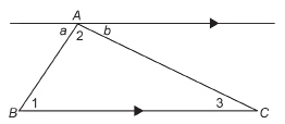
1.30. Page 5
Module 5: Angles
Lesson Summary
© Amid/shutterstock
At the turn of the twentieth century, there were movements away from painting pictures, which could, some argued, just as well be taken with a camera. One of those movements was cubism. Cubist paintings were no longer from one perspective. You can find out more about modern art through an Internet or library search.
In this photograph, the abstract background of light and dark incorporates parallel and convergent lines. Can you identify lines and angles formed by transversals? In this lesson you explored the following related question: How are the measures of angles determined in situations involving parallel lines and transversals?
Check your level of understanding of the materials covered in this lesson by completing “Lesson 6 Traffic Lights.” If you select an amber or red traffic light in the multimedia piece, you will receive information about additional work you can complete to improve your understanding of the topics. Complete the suggested work before you proceed to the Lesson 6 Assignment. If you experience difficulty, contact your teacher before starting the Lesson 6 Assignment.
You practised your skills at solving problem situations involving angles arising from the intersection of parallel lines. These problems involved vertically opposite angles, adjacent and supplementary angles, corresponding angles, alternate angles, and co-interior and co-exterior angles. Some of these angles were formed by perpendicular transversals.
 Assignment
Retrieve the Lesson 6 Assignment Booklet you saved in your course folder at the start of this lesson. Complete the Assignment. Resave your Assignment Booklet in your course folder and submit a copy to your teacher for assessment.
Unit 3 Project
Take a look back at the Focus section. You saw the parallel lines in the hockey rink with the puck intersecting the lines. Now view the shot in the “Billiard Shot” video clip. Do you see the parallel and perpendicular lines (the cushions) and the angle of the cue ball’s (white ball) path as it bounces?
Do some exploring of your project topic. Can you find parallel lines and transversals? Are they hidden and tricky to see, like in the game of pool, or are they a bit more obvious, as in the hockey example? Sketch and record what you have found, and keep this information to help you with your Unit 3 Project presentation.
1.31. Module 5 Summary
Module 5: Summary
© Canadian Museum of Civilization, no. V-Z-2, D2004-25928
The photograph displays the intricate beadwork on a MÉtis bag, which is one of the items in the collections at the Canadian Museum of Civilization. The bag is thought to have been made in the 1800s. If you look at the geometric patterns on this bag, you must agree that art and geometry go hand-in-hand. Within the pattern, you will see acute, right, obtuse, and congruent angles, and parallel and perpendicular lines. All of these angles and lines were addressed by the lessons in this module.
In this module you developed your skills as you investigated the following questions:
- How are angles defined, measured, classified, duplicated, and bisected?
- What are the relationships among the angles formed when two parallel lines are cut by a third line?
Throughout this module, you examined how the concepts from the lessons applied to games or art for your Unit 3 Project. A picture can tell a story. Think about your project as you review the “Module 5 Lessons Summary.” What do you remember about each image? Can you relate each image to something new you learned in this module?