Module 4
| Site: | MoodleHUB.ca 🍁 |
| Course: | Physics 30 SS |
| Book: | Module 4 |
| Printed by: | Guest user |
| Date: | Wednesday, 17 December 2025, 10:13 PM |
Description
Created by IMSreader
Table of contents
- 1. Module 4
- 1.1. Big Picture
- 1.2. In this Module
- 1.3. Lesson 1
- 1.4. Page 2
- 1.5. Page 3
- 1.6. Page 4
- 1.7. Page 5
- 1.8. Page 6
- 1.9. Lesson 2
- 1.10. Page 2
- 1.11. Page 3
- 1.12. Page 4
- 1.13. Page 5
- 1.14. Page 6
- 1.15. Page 7
- 1.16. Lesson 3
- 1.17. Page 2
- 1.18. Page 3
- 1.19. Page 4
- 1.20. Page 5
- 1.21. Page 6
- 1.22. Page 7
- 1.23. Module Summary/Assessment
- 1.24. Module Glossary
1. Module 4
Module 4—Magnetic and Electric Fields in Nature and Technology
© Matthew Jacques/shutterstock
Module Introduction
In Module 4 you will learn how the properties of electric and magnetic fields are observed in nature and applied in modern technologies. You will be asked to apply your knowledge to the following question:
-
How are magnetic fields and current-carrying conductors used to convert mechanical energy into electrical energy, and vice versa?
1.1. Big Picture
Module 4—Magnetic and Electric Fields in Nature and Technology
 Big Picture

© Walter S. Becker/shutterstock
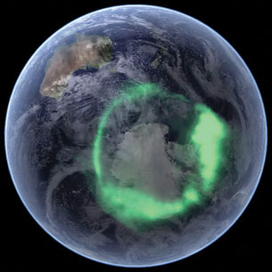
Image courtesy NASA
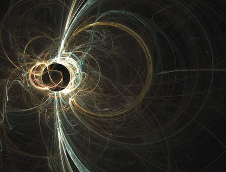
In the night sky of northern Alberta you can see some of the planet’s most fantastic light shows. The photograph on the left is of the aurora borealis (aka northern lights). The image on the right is of the aurora australis (aka southern lights) over Antarctica and was taken from space with Nasa’s IMAGE satellite. The aurora australis is overlaid on a clear image of NASA’s “Blue Marble.”
The auroras occur when some of the charged particles in the solar wind are trapped in Earth’s magnetic field. As they spiral downward along field lines they interact with atoms in the atmosphere. It is this interaction that results in the light show. Aside from being very beautiful, they were also responsible for some of the very early observations that linked electric and magnetic fields. For example, on September 2, 1859, a very intense solar wind (charged particles given off by the sun) created an aurora so bright that people could read outside at night. At exactly the same time, hundreds of thousands of kilometres of telegraph cable were disrupted and some lengths of it began to function without battery power. Apparently, whatever was creating the aurora was also creating a current in some of the telegraph cables. People began to suspect that electrical and magnetic phenomena were somehow linked.
Today the connection between electric and magnetic fields and forces is well understood and has led to innovations and technologies that support our lifestyle. Examples of this connection include the electrical generators and motors that are connected throughout the North American electrical grid.
In Module 4 you will explore power generation and consumption in devices such as generators and electrical motors.
© Igor Karon/shutterstock

© Brandon Blinkenberg/shutterstock
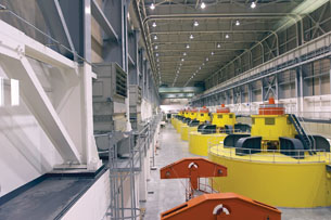
In the photograph on the left, turbines spin generators that convert mechanical energy into electrical energy. The photograph on the right shows an electric drill designed to convert the electrical energy produced by the generators back into mechanical energy that can be used to do work on other objects. How is this facilitated by the properties of electric and magnetic fields and forces?
By the end of Module 4 you will understand the interaction of electric and magnetic fields in the conversion of electrical and mechanical energy.
As you are working in Module 4, keep the following questions in mind:
-
What is the cause and nature of a magnetic field?
-
How are moving charges affected by a magnetic field?
- How are current-carrying conductors affected by magnetic fields?
 Module Assessment
Each lesson has a teacher-marked assignment, based on work completed in the lesson. In addition, you will be graded on your contributions to the Discuss section of each lesson.
You will also be asked to complete Self-Check or Try This questions, which you should place in your Physics 30 course folder. These are not formally assessed but are a valuable way to practise the concepts and skills of the lesson. These activities can provide you with reflective feedback on your understanding of the lesson work.
You will be marked for your lesson work on the following items:
-
Module 4: Lesson 1 Assignment
-
Module 4: Lesson 2 Assignment
-
Module 4: Lesson 3 Assignment
At the end of the module you will complete a module assessment that consists of two diploma-style written-response questions. The first question will assess your knowledge of charge-to-mass ratios, and the second question will assess your knowledge of electromagnetic induction. See the Module Summary and Assessment page for more information. If you have any questions contact your teacher.
1.2. In this Module
Module 4—Magnetic and Electric Fields in Nature and Technology
In This Module
Lesson 1—Magnetic Fields
In this lesson you will explore the source and direction of the magnetic field produced by permanent bar magnets and moving charges. You will compare and contrast electric, gravitational, and magnetic fields.
-
What is a magnetic field?
-
How is Earth’s magnetic field produced?
-
What is the significance of a current-carrying conductor inducing a magnetic field?
Lesson 2—Moving Charges in Magnetic Fields
In this lesson you will explore the effects of uniform magnetic and electric fields on moving charges. You will also investigate the application of magnetic forces in modern technology.
-
How is moving charge affected by a magnetic field?
-
What variables determine the magnitude of the magnetic force?
-
How is the direction of the magnetic force determined?
Lesson 3—Electromagnetic Induction
In this lesson you will explore the interaction between an external magnetic field and a current-carrying conductor. You will see the application of these interactions in the conversion of mechanical energy into electrical energy and vice versa.
-
What is the nature of the magnetic force acting on a current-carrying conductor in an external magnetic field?
-
How are magnetic forces used in a direct current motor?
-
How is a current produced by an electric generator
1.3. Lesson 1
Module 4—Magnetic and Electric Fields in Nature and Technology
Lesson 1—Magnetic Fields
 Get Focused
© RickParsons/shutterstock
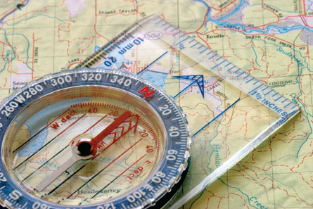
A compass is a navigational tool for identifying directions on Earth’s surface. It consists of a tiny magnetized “needle” which is free to rotate around a fixed point in the centre. Being free to move, it will align itself with Earth’s magnetic field. This fact makes a compass a useful tool for understanding position and direction of motion relative to a common, fixed point, such as the geographic North Pole of Earth.
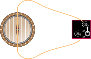
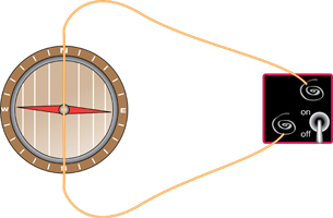
Another less known fact is what happens to a compass needle if you place it near a current-carrying wire. The needle will quickly swing around to a point perpendicular to the conductor. If the needle’s movement is a reaction to a current-carrying conductor, does that mean Earth is a giant conductor? How can Earth and a current-carrying conductor both have magnetic fields? What are magnetic fields and how are they produced?
In previous lessons you learned about gravitational fields and electric fields. In this lesson we will explore the magnetic field.
In this lesson you will answer the following essential questions:
-
What is a magnetic field?
-
How is Earth’s magnetic field produced?
-
What is the significance of a current-carrying conductor inducing a magnetic field?
 Module 4: Lesson 1 Assignment
Your teacher-marked Module 4: Lesson 1 Assignment requires you to submit a response to the following questions:
- Assignment—A 1, A 2, A 3, A 4, and A 5
- Discuss—D 3
The other questions in this lesson are not marked by the teacher; however, you should still answer these questions. The Self-Check and Try This questions are placed in this lesson to help you review important information and build key concepts that may be applied in future lessons.
After a discussion with your teacher, you must decide what to do with the questions that are not part of your assignment. You should record the answers to all the questions in this lesson and place those answers in your course folder.
1.4. Page 2
Module 4—Magnetic and Electric Fields in Nature and Technology
© Thomas Mounsey/shutterstock
 Explore
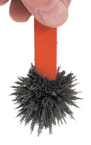
In the photo to the right, tiny iron filings cling to the end of a bar magnet. This should be no surprise since it is known that bar magnets can exert a force on other magnets and that some metals, such as iron, are easily attracted to bar magnets. This photo supports these observations. But it does more; the tiny bits of iron have collected along the lines of the magnetic field, hinting at its shape near the pole. As you will see in the Watch and Listen activities below, you can perform many other demonstrations to explore the nature of the magnetic field and reveal some of its properties.
magnetic field: a three-dimensional region of magnetic influence surrounding a magnet in which other magnets or magnetic substances are affected by magnetic forces
 Watch and Listen
The aurora is one of the greatest shows on Earth; it is caused by Earth’s magnetic field. But what is a magnetic field? As shown, a magnetic field can be observed by using bar magnets. Watch the video The Effect of Heat on Magnetism to see a magnetic field destroyed by heat and restored by cooling.
Magnetic Field of a Permanent Magnet
© Awe Inspiring Images/shutterstock
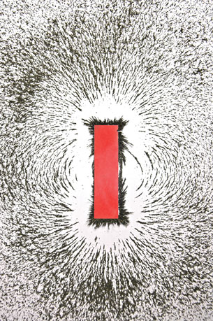
Each of the tiny filings of iron that are sprinkled near the bar magnet in the image above acts like a tiny compass. When the filings land they align themselves with the bar magnet’s magnetic field and reveal two dimensions of its shape. Like the electrical field between two oppositely charged point charges, the magnetic field has two poles, one at either end of the bar magnet. Like electric charges, like poles repel and unlike poles attract. The field is three-dimensional in nature, as observed in the interactive tutorial that follows.
 Try This
Note that the Try This activity is critical and presents important information that will be required later in this lesson and in the Module Assessment.
Explore the magnetic field surrounding a bar magnet using the interactive tutorial Magnetic Fields. Remember that magnetic “field lines” are mental constructs used to visualize the field; they are not physical entities. Be sure to notice the use of small compasses in the tutorial.
TR 1.
-
Draw a bar magnet, labelling the north and south poles. Sketch the magnetic field surrounding it, making sure your arrows point in the right direction. How is the direction of this field determined?
-
How does the density of the magnetic field lines relate to the field strength?

© Thomas Mounsey/shutterstock
When two bar magnets are placed near one another, the fields interact. The absence of filings between the poles in this photo is an indication of opposing magnetic fields. In this case, the two magnets are repelling one another. Perhaps you can see the field lines between the two magnets as almost perpendicular to the lengths of the magnets.
TR 2. Explore the magnetic field surrounding two bar magnets and how to represent magnetic fields in three dimensions using the interactive tutorial Two Magnets. What you draw on paper for a magnetic field depends on your point of view. Summarize the three different magnetic field representations.
Recall that in previous lessons the gravitational and electric fields were described by three-dimensional regions of influence. The magnetic field shares this similarity.
tesla: a unit of magnetic field strength (T) defined as one ![]() or one
or one ![]()
The magnetic field is a vector field and its direction is the direction the north (south-seeking) end of a compass will point when it is located in the magnetic field. Magnetic field strength is the magnitude of the magnetic field. Magnetic field strength is measured in a unit called the tesla (T). A tesla is defined as one ![]() or one
or one ![]() .
.
Magnetic fields tend to be stronger near the poles of magnets (or near Earth's poles). Earth's magnetic field strength in this region is about 6 × 10⁻⁵ T. A typical 10-g bar magnet has a magnetic field near its poles of about 2 × 10⁻² T.
On occasion you may also see the strength of a magnetic field described using the term “flux.”
 Self-Check
SC 1. Each diagram shows two equal-strength bar magnets with test objects around them. Indicate the polarity of the bar magnets in each diagram.
![]()
a. ![]()
b. ![]()
c. 
d. 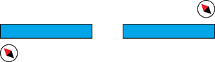
SC 2. Each diagram shows two equal-strength bar magnets. Draw the magnetic field lines that would surround the pair of magnets.
a. ![]()
b. ![]()
c. 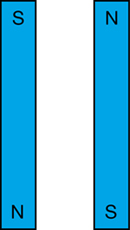
d. 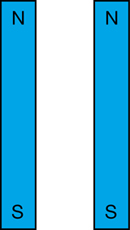
Self-Check Answers
SC 1. Contact your teacher if your answers vary significantly from the answers provided here.
a. ![]()
b. ![]()
c.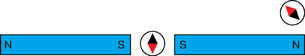
d. 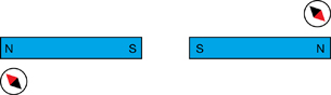
SC 2. Your field lines should look similar to those shown below.
a. 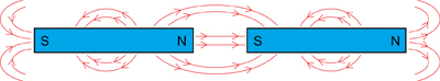
b. 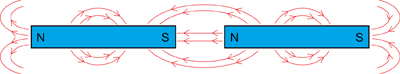
c. 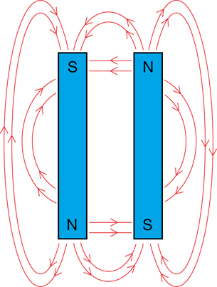
d. 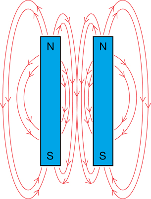
1.5. Page 3
Module 4—Magnetic and Electric Fields in Nature and Technology
Earth‘s Magnetic Field
Earth’s magnetic field is similar to that of a bar magnet. Compare the two magnetic fields illustrated below. Notice that the magnetic south pole of Earth exists near the geographic North Pole.
This explains why the “north” magnetic pole of a compass is attracted to the geographic “North” Pole of the planet—which is really the “south” magnetic pole when you consider Earth as a giant bar magnet.

The source of this material is Windows to the Universe, at http://www.windows.ucar.edu/ at the University Corporation for Atmospheric Research (UCAR). © The Regents of the University of Michigan; All Rights Reserved.
Magnetic Fields and Moving Charge—The Cause of Magnetism
On April 21, 1820, Hans Christian Ørsted (1777–1851) was preparing for an evening lecture when he noticed that a nearby compass needle was deflected when an electric current from the battery he was using was switched on and off. The deflection of a compass needle near an electric current confirmed that a magnetic field is produced by moving charge, indicating a direct relationship between electricity and magnetism.
 Watch and Listen
Watch the following video clip that explains the effect of an electric current on a compass needle. Describe the materials, setup, and procedure shown in the video Ørsted’s Discovery—Magnetic Fields. What did you observe?
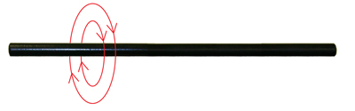
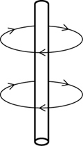
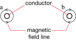
Ørsted had discovered that an electric current passing through a wire produces a circular magnetic field that surrounds the wire.
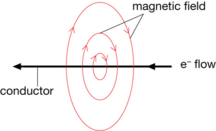
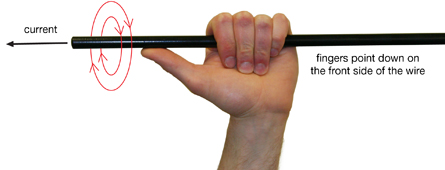
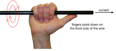
The direction of the magnetic field surrounding a current-carrying conductor can be determined using the “left-hand rule for current-carrying conductors.” This rule states the following:
Grasp the conductor with your left hand, such that your thumb points in the direction that the electrons are flowing. Your fingers will curl around the wire in the direction that the magnetic field follows.
There is also a right-hand rule for moving positive charges:
Grasp the conductor with your right hand, such that your thumb points in the direction that the positive charges are flowing. Your fingers will curl around the wire in the direction that the magnetic field follows.
magnetic flux: the number of magnetic field lines passing through a given area perpendicular to the field
solenoid: an electromagnet that operates a mechanical device by using the magnetic field produced by a current-carrying conductor wrapped into a coil
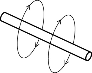
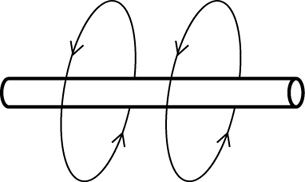
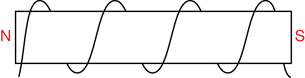
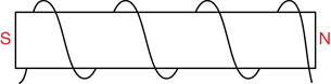
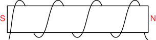
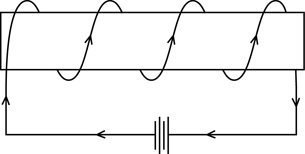
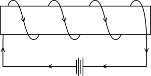
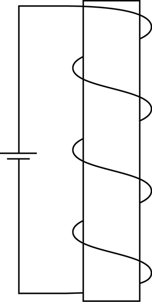
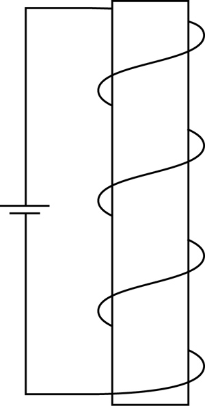
The magnetic field around a single wire is not always strong enough for practical applications (such as electromagnets). The intensity (magnetic flux) of the magnetic field can be increased by wrapping the current-carrying conductor around a tube numerous times to create a solenoid.
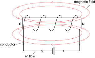
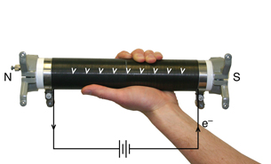
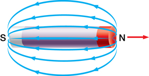
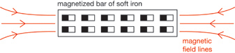
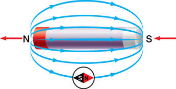
In this orientation the magnetic field of each coil on the tube contributes, in an additive manner, to the intensity of the magnetic field. Notice that inside the tube, the magnetic field is directed from the south pole to the north pole and that outside the tube it completes the loop, pointing from the north to the south pole.
Compare this with the magnetic field produced by a regular bar magnet.
The direction of the magnetic field “inside” the solenoid is determined, again, with a hand rule.
Grasp the coil with your left hand, such that your fingers curl around the coil in the same direction the current flows. The extended thumb will indicate the direction of the magnetic field within the coil.
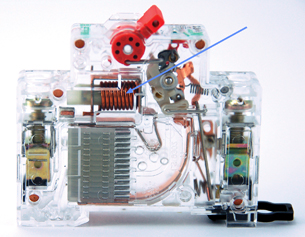
© CHEN HENG KONG/shutterstock
A common application of the solenoid is the electromagnet, a mechanical device for moving metal objects and operating remote switches. In the photo to the right notice the small copper solenoid in the clear circuit breaker just below the red switch. When there is too much current moving in the circuit attached to this breaker, the magnetic field produced by the solenoid becomes strong enough to mechanically disconnect the circuit and stop the current.
According to the behaviour of a compass near a current-carrying conductor, the cause of magnetism is related to the movement of charge. Does this mean that moving charge is the cause of Earth’s magnetic field?
Watch and Listen
Is moving charge the source of Earth’s magnetic field? Watch the video clip Earth’s Magnetic Field to find out.
1.6. Page 4
Module 4—Magnetic and Electric Fields in Nature and Technology
 Read
Read
There are many devices that use electromagnets. Some common ones are explained in the document “Applications of the Electromagnet.” More information on hand rules and electromagnets can be found on pages 587–589 of the textbook.
 Module 4: Lesson 1 Assignment
Remember to submit the answers to A 1, A 2, A 3, A 4, and A 5 to your teacher as part of your Module 4: Lesson 1 Assignment.
A 1. Using the diagrams below, indicate the direction of the magnetic field associated with the wire when the current is flowing in the direction indicated. (Electron current flows from negative to positive.)
a.
![]()
b.
![]()
d.
![]()
e.
![]()
A 2. Using the diagrams below, indicate the direction of electron flow if the associated magnetic field is in the direction indicated.
a.
b.
c.
A 3. Given the diagram below, indicate whether a dot or an “x” should be placed in each circle. (Note that current is the direction of the electrons, e- flow.)
A 4. Given the diagrams below, indicate the path of the current (e- flow) that produces magnetic poles as indicated.
a.
b.
c.
A 5. Given the diagrams below, indicate the direction of the magnetic field created by the current (e- flow) flowing through the solenoid.
a.
b.
c.
d.
e.

Domain Theory
If magnetic fields are produced by moving charges, how is it possible to understand the magnetic field produced by a permanent bar magnet? Furthermore, how can it explain why heating a piece of iron will cause it to not be attracted to a magnet, but the attractive force will return when the piece of iron is cooled? Revisit the first Watch and Listen activity of this lesson, if needed, to see the demonstration of how heating and cooling destroys and restores the magnetic properties of iron.
ferromagnetic material: a metal with adjacent atoms having electron movement that, taken together, form a small region with an intense magnetic field
Examples include iron, nickel and cobalt.
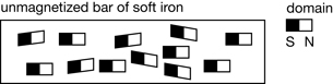
domain: the region of a material in which the magnetic fields of most of the atoms are aligned
As you learned in previous lessons, the moving charges associated with matter are the electrons. In some atoms the electron movement generates a very small magnetic field. Ferromagnetic material—such as iron, nickel, and cobalt—has many adjacent atoms with electron movement that, taken together, form a small region with an intense magnetic field.
Each region, about 1 mm across, contains billions of atoms and is referred to as a domain. Within the domain, the tiny magnetic field associated with the movement of each electron is additive, producing a significant magnetic field. When all the domains of a bar magnet, for example, align together, it is said to be magnetized. When the domains are erratically arranged they cancel one another out and the overall magnetic properties no longer exist.
The domain model helps explain the effect of heat on the magnetic properties of a permanent iron magnet. When heated, the atoms composing the domains become agitated and the electron movement changes, effectively destroying the alignment of the domains, so the iron loses its magnetic field. When the iron cools, the unaligned domains are locked in place and the magnet is a regular piece of iron.
To change the piece of iron back into a permanent magnet it must be heated, which frees the domains to change alignment, placed in a strong external magnetic field and cooled. The external magnetic field causes the excited domains to align and they are locked into position as the iron cools. The domains of the piece of iron are aligned again and it becomes a magnet again.
The domain theory also explains why non-magnetized materials, such as iron, can become magnetized in the presence of another magnet. The magnetic field lines emanating from a permanent magnet can cause the alignment of some of the domains that exist in other metals, thereby giving them magnetic properties too. This explains why metal containing iron or nickel are attracted to permanent magnets. The external magnetic field causes an alignment of some of the domains in the iron or nickel, giving it weak magnetic properties, which can then interact with the external magnetic field that caused the alignment. When the magnet is moved away from the iron, the domains quickly lose their alignment and the iron is non-magnetic again.
 Try This
TR 3. Complete “Check and Reflect” questions 7–13 on page 592 of the textbook.
For question 10, make sure you think about two things in each case: (1) what is the source of the field, and (2) what is the test object?
 Discuss
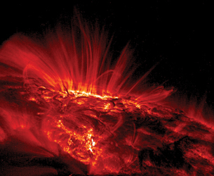
NASA/LMSAL
The Sun has a very complex magnetic field, caused by its rotation and the moving charge within its core. In the photograph to the right, erupting material can be seen emanating from the surface of the Sun, following the magnetic field in the region. The complex magnetic field can also be observed in sunspots – regions on the surface of the Sun marked by lower temperatures and intense magnetic fields.
Sunspot activity follows an 11-year cycle as the magnetic poles of the Sun reverse in orientation. The intense magnetic field associated with sunspots also ejects massive amounts of material in the form of solar flares that can be carried along in the solar wind, creating outages in electrical equipment on Earth when it arrives. A good example of this was the massive aurora in September 1859 that electrified telegraph cables in North America, which was referred to in the Module Introduction.
D 1. Research the Sun’s magnetic field and respond with a few paragraphs to address the following items:
-
Explain the role of the magnetic field in producing sunspots.
-
Explain how both poles of the magnetic field are observed in sunspots.
-
Explain why it is important to understand the nature of sunspots and the Sun’s magnetic field in general.
-
Explain, in terms of the study of physics, why you believe that the sources you found on the Internet are reliable.
Begin your research by watching the video clip Earth’s Magnetic Field again. Then use your Internet search skills to find at least two more articles or videos that apply.
D 2. Post your findings in the discussion area for your class and read at least two other postings.
Module 4: Lesson 1 Assignment
Remember to submit the answer to D 3 to your teacher as part of your Module 4: Lesson 1 Assignment.
D 3. Revise your response to D 1 using the additional information from your readings of other students’ work and comment on how reading their work improved your own.
| Principles involved: magnetic fields, charged particles in a magnetic field | ||||
Criteria |
Level 1 |
Level 2 |
Level 3 |
Level 4 |
Knowledge |
||||
Demonstrates understanding of the situation, physics principles and technology, and their connections. |
Demonstrates a vague and sometimes incorrect understanding of the physics principles involved. Obvious irrelevant or missing information. |
Demonstrates a basic understanding of the physics principles involved. May exhibit minor mistakes or vague information or application to the situation. |
Demonstrates a good understanding of the physics principles involved and applies them properly to the given situation. All necessary information is given. |
Demonstrates a superior understanding of the physics principles involved and their application to the situation. All applications are considered in detail. |
Reflection |
||||
The post shows reflection on one’s own and other students’ work. Contributes to the group discussion. |
Does not make an effort to participate. Seems indifferent to discussion. |
Occasionally makes meaningful reflections on the group’s efforts or discussions. Marginal effort is shown to become involved with the group or discussion. |
Frequently makes meaningful reflections on the group’s efforts and presents relevant viewpoints for consideration by the group. Interacts freely with group members. |
Regularly attempts to motivate the group discussion and delve deeper into concepts. Interacts freely and encourages all group members. |
Content and presentation of discussion summary |
||||
The information is logically arranged in a clear and concise manner. |
The information is poorly organized with many concepts implied. Irrelevant or rambling sentences make reading difficult. |
The information is somewhat organized with implied concepts. Excessive words or awkward sentences are used, which hinder reading. |
The information is well-organized and logically arranged. All concepts are explicitly explained. There are a few awkward but understandable sentences. |
The information is well-organized and very easy to understand. Well-worded sentences make reading pleasurable. |
1.7. Page 5
Module 4—Magnetic and Electric Fields in Nature and Technology
 Reflect and Connect

© Craig Mills/shutterstock
The movement of charge in Earth’s core, affected by the spin of the planet, generates a magnetic field. Since the motion of the molten iron and nickel in Earth’s core is fluid and changing, so too are the locations of the north and south magnetic poles. The location of the poles changes very slowly, over a long period of time. For example, if you travelled magnetically north today, and then did the same 10 years later, you would, in fact, be going in slightly different directions.
This has important implications for compass-based navigation. Runway numbering is an example of the application of compass-based navigation. Runway numbers are traditionally assigned based on their directions relative to the magnetic north pole. Since the pole is moving, runway numbers are periodically reassigned. Can you think of any other problems a moving magnetic pole could create?
Reflect and Connect
The orientation of a compass needle near a current-carrying conductor is a very simple observation with astounding implications. It confirms that electrical currents can produce magnetic forces and that the two phenomena are, therefore, connected. This opens up the study of “electromagnetism” and the development of generators and motors. Complete the following activity and save your response to your course folder.
RC 1. Compare the shape of Earth’s magnetic field with one produced by a current-carrying solenoid or closed loop of wire. Sketch the fields and explain how Earth’s field is created using terminology associated with the loop of wire.
 Module 4: Lesson 1 Assignment
Remember to submit the Module 4: Lesson 1 Assignment to your teacher.
1.8. Page 6
Module 4—Magnetic and Electric Fields in Nature and Technology
 Lesson Summary
In this lesson you focused on the following essential questions:
-
What is a magnetic field?
-
How is Earth’s magnetic field produced?
-
What is the significance of a current-carrying conductor inducing a magnetic field?
The magnetic field of a bar magnet can be represented by magnetic field lines. The density of lines at a given point indicates the intensity of the field at that point.
Compass needles align themselves with the direction of the magnetic field. The magnetic field surrounding a bar magnet is from north to south.
When a compass is placed in a magnetic field, the north pole of the compass needle points in the same direction as the field.
Arrows are used to indicate the direction of a magnetic field line.
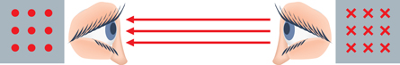
In three dimensions, magnetic field lines coming towards the observer are represented with dots and those going away from the observer are represented with x’s. The arrows are symbolic representations since the magnetic field is invisible to the eye.
Magnetic fields are produced by moving charge, according to Ørsted’s observations that a circular magnetic field surrounds a current-carrying conductor. The directions of the magnetic field surrounding a current-carrying wire or through a coil of wire (solenoid) can be identified using hand rules.
All magnetic fields can be explained by the motion of moving charges. Earth’s magnetic field is created by the motion of molten iron and nickel in Earth’s core. The magnetic properties of a permanent magnet are explained using domain theory, which relates the synchronized motion of electrons in small chunks of ferromagnetic material like soft iron.
The connection between moving charge and the production (induction) of magnetic fields is the first step in understanding electromagnetism that is observed in nature and used in modern technologies, such as electrical generators and motors.
Lesson Glossary
domain: the region of a material in which the magnetic fields of most of the atoms are aligned
ferromagnetic material: a metal with adjacent atoms having electron movement that, taken together, form a small region with an intense magnetic field
magnetic field: a three-dimensional region of magnetic influence surrounding a magnet in which other magnets or magnetic substances are affected by magnetic forces
magnetic flux: the number of magnetic field lines passing through a given area perpendicular to the field
solenoid: an electromagnet that operates a mechanical device by using the magnetic field produced by a current-carrying conductor wrapped into a coil
tesla: a unit of magnetic field strength (T) defined as one ![]() or one
or one ![]()
1.9. Lesson 2
Module 4—Magnetic and Electric Fields in Nature and Technology
Lesson 2—Moving Charges in Magnetic Fields
 Get Focused
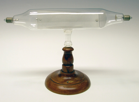
The cathode ray tube (CRT) consists of a glass tube from which air has been removed, with an electrode inserted at each end. When a very large voltage is applied to the electrodes a cathode ray is produced. In this photo the cathode ray is contacting a fluorescent material that coats the metal sheet inside the evacuated tube. With this kind of technology and the aid of a magnetic field, J.J. Thompson was able to discover the electron in 1897.
Today, the most commonly used cathode ray tube is an old-fashioned television set. Glass-tube televisions are no longer produced in vast quantities as newer plasma, LCD, and other display technologies have replaced most of the market share with compact, higher-resolution systems. The cathode ray tube, however, remains a very important stepping-stone on the way to developing theories about electromagnetism.
![]()
The Cathode Ray Tube Site
http://members.chello.nl/h.dijkstra19
It was initially explored using magnetic fields, which deflected the ray in various directions, depending on the orientation of the beam and the magnet. In the photograph on the left there is no magnetic field. In the middle photograph the beam is deflected by a magnetic field perpendicular to the beam. The photograph on the right is the beam when the magnetic field has been reversed. The deflection of the beam when it is in a magnetic field indirectly indicates that the beam is made up of negative charges. How could this conclusion be reached?
Recall from Module 3: Lesson 4 that at sufficient voltages, the air separating two electrodes will ionize, temporarily allowing the passage of charge (electrons) in the form of a spark. This is what you would experience if you rubbed sock feet on a carpet and then touched a doorknob. In a cathode ray tube, most of the air has been removed and the residual gas becomes ionized by the electron beam. The spark mentioned in Module 3: Lesson 4 becomes a “current” of moving charges for as long as the voltage is maintained. The glow results from the interaction of the moving charge with fluorescent coatings in the tube.
Recall from Lesson 1 in this module that a moving charge will produce a circular magnetic field that surrounds the charge and is perpendicular to its motion. Therefore, if the cathode ray is indeed a moving charge, a circular magnetic field will surround it. Now imagine what happens when a second, external, magnetic field is present. Like two magnets repelling one another, the two fields interact to produce a magnetic force on the moving charge. This force repels the charges and creates a deflection of their movement. (See “Figure 12.16” on page 594 of the textbook.) In addition, the direction of this force is indicative of the type of charge. The cathode ray, it turns out, is a beam of moving electrons, negatively charged according to the deflection caused when it encounters an external magnetic field. You can read more about this in “The Motor Effect” on pages 593−595 in your textbook.
In this lesson you will answer the following essential questions:
-
How is moving charge affected by a magnetic field?
-
What variables determine the magnitude of the magnetic force?
-
How is the direction of the magnetic force determined?
 Module 4: Lesson 2 Assignment
Your teacher-marked Module 4: Lesson 2 Assignment requires you to submit a response to the following questions:
- Assignment—A 1, A 2, A 3, A 4, A 5, and A 6
- Discuss—D 3
The other questions in this lesson are not marked by the teacher; however, you should still answer these questions. The Self-Check and Try This questions are placed in this lesson to help you review important information and build key concepts that may be applied in future lessons.
After a discussion with your teacher, you must decide what to do with the questions that are not part of your assignment. You should record the answers to all the questions in this lesson and place those answers in your course folder.
1.10. Page 2
Module 4—Magnetic and Electric Fields in Nature and Technology
 Explore

© Roman Krochuk/shutterstock
In the photograph to the left, the aurora borealis lights up the northern night sky. Compare this photo with the cathode ray photos from Get Focused in Lesson 2. There are some similarities. Both phenomena are related by the motion of a moving charge in an external magnetic field. In the cathode ray pictures, the external magnetic field originates from a bar magnet and acts on moving electrons that make up the beam. Here, Earth’s magnetic field acts as an external magnet, affecting the motion of charged particles in the solar wind. The motion is very predictable but can also be complex. A simulation will be used to observe and understand the motion of a charged particle in a magnetic field.
 Try This—Part 1: The Force Exerted by a Magnetic Field on a Charged Particle
Open the “Particle in a Magnetic Field” simulation.
Before making any observations on the simulation, recall that a magnetic field is a vector quantity having magnitude and direction. The simulation can show three different directions for the magnetic field using the following notation, which was introduced in the tutorials of Module 4: Lesson 1.
![]() - magnetic field directed into the page/screen
- magnetic field directed into the page/screen
![]() - magnetic field directed out of the page/screen
- magnetic field directed out of the page/screen
![]() - magnetic field directed to the right on the page/screen
- magnetic field directed to the right on the page/screen
All other directions, of course, are possible but are not shown or used in the simulation.
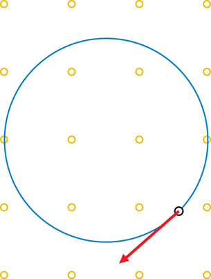
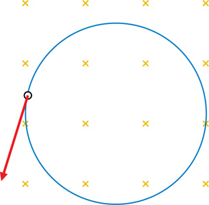
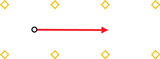
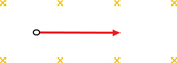
TR 1. In the simulation, set the magnetic field direction as indicated by the small yellow arrows, dots or x’s in each image below, turn on “trace” (![]() ), and press “play.” The large magenta (purplish red) arrow is the initial velocity of the charged particle. Sketch the path of the particle on each image below:
), and press “play.” The large magenta (purplish red) arrow is the initial velocity of the charged particle. Sketch the path of the particle on each image below:

-
Which path is characteristically different than the other two?
-
In which two situations above is the magnetic field perpendicular to the particle's velocity?
-
What type of motion is exhibited when the magnetic field is perpendicular to the particle's velocity?
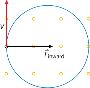
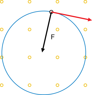
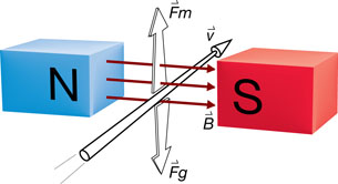
Figure 1
In both b. and c., the charged particle exhibits circular motion. Recall that in uniform circular motion an inward force is required to maintain the constantly changing direction of the particle. In this case, that force is acting due to the magnetic field when the charged particle moves perpendicular to the direction of the magnetic field (b. and c. above).
The inward force is illustrated in Figure 1.
If the initial velocity and magnetic field are in the same direction no magnetic force is produced, so the charge’s velocity does not change (straight line movement). If the initial velocity and magnetic field are perpendicular, an inward magnetic force will cause circular motion.
1.11. Page 3
Module 4—Magnetic and Electric Fields in Nature and Technology
 Read
Read
See “Charged Particle Motion in a Magnetic Field” on pages 596−597 of the textbook for further explanation and illustrations of the magnetic force.
 Try This—Part 2: The Force Exerted by a Magnetic Field on a Charged Particle
Problem
On what physical quantities does the force exerted on a particle in a magnetic field depend, and how does it depend on these quantities?
Background Information
The simulation in Part 1 of this Try This activity can be used to determine the relationship between the magnetic force and the following quantities:
-
(m) mass of the particle
-
(q) charge of the particle
-
(
 ) velocity of the particle
-
(
 ) magnetic field strength
To establish a relationship between the magnetic force and any one variable (the responding variable), you would change one variable at a time (the manipulated variable) and observe any resulting changes in the magnetic force. With all other variables held constant, a change in one variable and a corresponding change in the magnetic force would indicate a relationship. The amount of change would further indicate the nature of the relationship.
In order to test the relationship between the magnetic forces and each of the four quantities listed above, there needs to be a way of measuring the force. Newton's second law provides such a way.
Newton's Second Law F = ma (1)
In uniform circular motion, the magnitude of the acceleration a is equal to equation (2), where r is the radius of the circular orbit and v the particle's constant speed.
Substituting equation (2) into equation (1) gives a measure of the magnitude of the magnetic force.
The simulation displays the value of r. In the laboratory, you would be able to measure r and manipulate the values of m and v. Therefore, you can measure the magnetic force by determining the value of the right side of equation (3).
The nature of the relationship is further revealed by graphing the effect of the changing variable on the magnetic force (the force is determined based on equation (3), using the radius of the particles’ path in the magnetic field). The shape of the following reference graphs reveals the relationship between two variables.
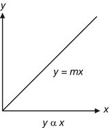
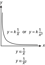

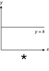
*The horizontal line indicates that the function is a constant. In this specific case the relationship is that mass does not affect the magnitude of the magnetic force.
Procedure
-
Open the simulation of a Particle in a Magnetic Field.
-
On the simulation, set the mass, speed, charge, and magnetic field strength as follows:
m = 1.0
v = 150
q = 1.0
= magnitude 100, direction out of screen
-
Play the simulation and record the value of r in Table 1. Press the data button to display the radius and period of motion.
-
Using equation (3),
 , calculate the magnitude of the magnetic force based on the radius. Add this value to Table 1.
-
On the simulation, click “rewind” (
 ), and double the mass (m = 2). Make no other changes.
-
Play the simulation and record the value for the radius of the path (r).
-
Calculate the magnetic force again.
-
Complete Table 1 by sequentially changing the value of the mass and recording the new radius and magnetic force.
-
Repeat steps 2 to 8 to complete the remaining data tables for the effects of velocity, charge, and magnetic field strength on the magnitude of the magnetic force. Vary only one variable at a time.
Observations
Table 1: How Mass Affects Force
Mass of Particle (m) |
Radius of Path (r) |
Magnetic Force from Equation (3) (Fm) |
1 |
|
|
2 |
|
|
3 |
|
|
Table 2: How Speed Affects Force
Speed of Particle (v) |
Radius of Path (r) |
Magnetic Fforce from Equation (3) (Fm) |
150 |
|
|
200 |
|
|
250 |
|
|
300 |
|
|
Table 3: How Charge Affects Force
Charge (q) |
Radius of Path (r) |
Magnetic Force from Equation (3) (Fm) |
1 |
|
|
2 |
|
|
3 |
|
|
Table 4: How Magnetic Field Strength Affects Force
Magnetic Field Strength (B) |
Radius of Path (r) |
Magnetic Force from Equation (3) (Fm) |
100 |
|
|
150 |
|
|
200 |
|
|
250 |
|
|
300 |
|
|
Analysis
-
Graph each variable versus the magnetic force. The manipulated variable is on the x-axis and the responding variable (the magnetic force) is plotted on the y-axis. Label each graph and draw the line of best fit. Alternatively, you may choose to build your graphs in Excel and insert them.
-
According to the mass versus magnetic force graph, is the magnetic force affected by the mass of the charged particle? State the mathematical relationship.
-
According to the speed versus magnetic force graph, is the magnetic force affected by the speed of the charged particle? State the mathematical relationship.
-
According to the charge versus magnetic force graph, is the magnetic force affected by the charge of the charged particle? State the mathematical relationship.
-
According to the magnetic field versus magnetic force graph, is the magnetic force affected by the strength of the magnetic field in which the particle travels? State the mathematical relationship.
-
Combine the results of questions 2 to 5 to produce an equation that describes the magnetic force in terms of the particle’s charge, velocity, and the strength of the external magnetic field that it moves in.
-
Manipulate your equation from question 6 to isolate for the term for the magnetic field (B). What is one way to express the units of the tesla? You will revisit these units in Lesson 3 in relation to the definition of current.
Save your completed observation tables and responses to all Analysis questions in your course folder.
Magnetic Force: The deflecting magnetic force acting on a charged particle moving through a magnetic field is proportional to the product of the particle’s speed (perpendicular to the magnetic field) and charge and the strength of the magnetic field in which it moves.
Expressed as an equation,
![]() (4)
(4)
| Quantity | Symbol |
SI Unit |
magnetic force |
F |
N |
charge of the particle |
q |
C |
speed of the particle |
v |
m/s |
strength of the magnetic field |
B |
T (tesla) |
The unit of the magnetic field strength, the tesla (T), is chosen so that the proportionality constant in equation (4) is 1. The size of the tesla is defined by equation (4).
Can you see that the following five quantities are equivalent?
![]()
Note: In 1948 the Bureau International des Poids et Mesures decided that the ampere is a base unit and not the coulomb.
1.12. Page 4
Module 4—Magnetic and Electric Fields in Nature and Technology
 Read
Read
Refer to pages 598−600 of the textbook for an explanation of how to calculate the magnetic force acting on a charged particle.
 Self-Check
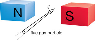
Experiments were conducted to see if flue gases from a power plant could be cleaned using a magnetic field. In one experiment with particles of mass 2.0 × 10⁻²⁰ kg, and speed of 1.50 × 10⁻² m/s, the following data was collected:
Charge on Particle (×10–17 c) |
Radius of Curvature (×10–3 m) |
1 |
150 |
2 |
75 |
3 |
50 |
4 |
36 |
5 |
30 |
10 |
15 |
Use the data to answer the following questions.
SC 1. Graph the data and draw a best-fit curve through the data points.
SC 2. Is there an easy way for you to find the magnetic field strength from this information?
SC 3. Graph the data using the reciprocal of the charge in place of the charge and draw a best-fit curve through these data points.
SC 4. Is there an easy way for you to find the magnetic field strength from this new graph?
Self-Check Answers
Contact your teacher if your answers vary significantly from the answers provided here.
SC 1. You can graph the data in several ways. You might
-
use graph paper and plot the points by hand
-
use a graphing calculator to graph the points
-
use a spreadsheet to graph the points
This graph uses a spreadsheet to graph the points. You may think of better titles for the graph and labels for the axes when you create your own graphs.
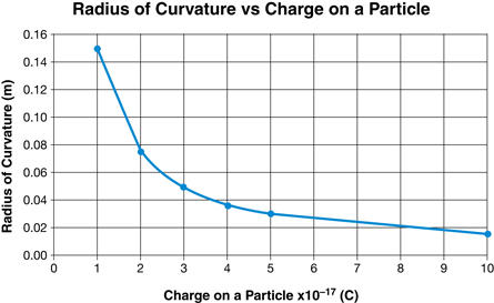
SC 2. With a curved graph, it is difficult to find the magnetic field strength.
SC 3. Again, the data can be graphed in several ways. This graph uses a spreadsheet to graph the points. You may think of better titles for the graph and labels for the axes when you create your own graphs.
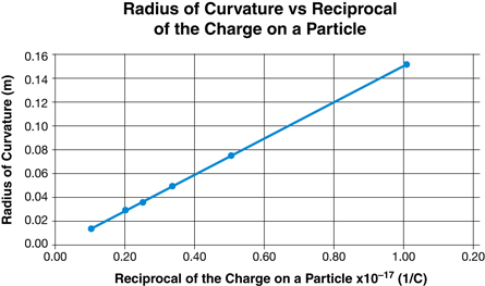
SC 4. This graph is a straight line. The slope of this graph gives an easy way to find the magnetic field strength. The slope is equivalent to ![]() , so the magnetic field strength can be found from
, so the magnetic field strength can be found from ![]() .
.
In this self-check question you used curve straightening to get useful information. You should consider using this technique whenever you need more information from a curved graph.
The Direction of the Magnetic Force
As you discovered earlier, the magnetic force causes the charged particle to travel in uniform circular motion.
 Module 4: Lesson 2 Assignment
Remember to submit the answers to A 1 to your teacher as part of your Module 4: Lesson 2 Assignment.
A 1. As a review, draw the inward force on the following diagrams. The first one has been completed as an example.
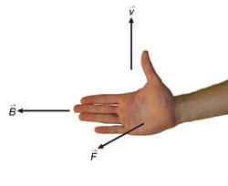
When a charged particle is moving at right angles to a magnetic field, the force exerted on the particle by the field is perpendicular to both the particle's velocity and the magnetic field. Refer again to the diagram on page 594 of the textbook. It may help to think of it this way: two of the quantities will be in the same plane of motion (able to be drawn on the same piece of paper) and the third will be into or out of that plane (the piece of paper).
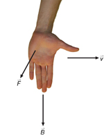
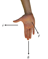
To predict the direction of the magnetic force, one only needs to know the direction of the particle's velocity and the direction of the magnetic field. However, this does not completely define the direction of the force. There is still an ambiguity because a perpendicular has two directions. This ambiguity is resolved by the left-hand rule illustrated in Figure 2. (There are several hand rules for this purpose. The following is only one suggestion.)
Left-hand Rule for Deflection: The direction of the force exerted on a negatively charged particle moving in a magnetic field can be visualized by the left-hand rule.
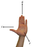
Figure 2
Hold your left hand flat with outstretched fingers in the direction of the magnetic field (![]() ) and with the thumb pointing off to one side in the direction of the particle's velocity (
) and with the thumb pointing off to one side in the direction of the particle's velocity (![]() ). The palm of your hand will then be pointing in the direction of the magnetic force (
). The palm of your hand will then be pointing in the direction of the magnetic force (![]() ).
).
This left-hand rule predicts the force that would act on negative charge. For a positive charge, use your right hand with your fingers, thumb, and palm representing the same quantities.
Example Problem 1.
A negatively charged particle is travelling right in a magnetic field that is directed downward.
-
Is the magnetic force “out of” or “into” the plane of the page?
-
If the particle where positively charged, in what direction would the magnetic force point?
Solution
-
According to the left-hand rule, the force is directed “out of” the plane of the page.
-
For a positive charge, using your right hand, the force would be “into” the plane of the page.
Example Problem 2.
A positively charged particle is travelling left in a magnetic field that is directed downward.
-
Is the magnetic force “out of” or “into” the plane of the page?
-
If the particle where negatively charged, in what direction would the magnetic force point?
Solution
-
According to the right-hand rule, the force is directed “out of” the plane of the page.
-
For a negative charge, using your left hand, the force would be “into” the plane of the page.
Module 4: Lesson 2 Assignment
Remember to submit the answers to A 2 to your teacher as part of your Module 4: Lesson 2 Assignment.
A 2. Predict, draw, and verify the magnetic force on each diagram below. Verify your answers using the simulation.
a. positive charge
b. positive charge
c. negative charge
d. negative charge
A combination of both equation (4) and the appropriate hand rule can be used to determine the magnitude and direction of the magnetic force acting on a moving charged particle. You will need to refer to your physics data sheet for the charge of an electron, proton, and alpha particle. Note the definition of the following terms that apply to the practice problems that follow:
-
“upward” means “out of” the plane of the page (
 ) (not to be confused with the term “north”)
 -
“downward” means “into” the plane of the page (
 ) (not to be confused with the term “south”)
Example Problem 3.
Calculate the magnitude and direction of the magnetic force acting on a proton travelling north at a speed of 2.75 × 10³ m/s through magnetic field of 3.50 × 10⁻¹ T that is directed west.
Magnitude
Fm = qvB
Fm = (1.60 × 10⁻¹⁹ C)(2.75 × 10³ m/s)(3.50 × 10–1 T)
Fm = 1.54 × 10⁻¹⁶ N
Direction
According to the right-hand rule for positive charges, the force is upward.
Self-Check
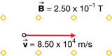
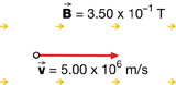
SC 5. Based on the following diagram, predict the magnitude and direction of the magnetic force acting on each proton. You can only verify the direction using the simulation.

Self-Check Answers
SC 5.
a.
direction: south
Fm = qvB
Fm = (1.60 × 10⁻¹⁹ C)(8.50 × 10⁴ m/s)(2.50 × 10–1 T)
Fm = 3.40 × 10⁻¹⁵ N
b.
direction: north
Fm = qvB
Fm = (1.60 × 10⁻¹⁹ C)(7.65 × 10⁵ m/s)(5.00 × 10–1 T)
Fm = 6.12 × 10⁻¹⁴ N
c.
Direction: none
magnitude: none −the motion and field direction are parallel.
1.13. Page 5
Module 4—Magnetic and Electric Fields in Nature and Technology
 Watch and Listen
Complete the Force on a Charge tutorial to explore the nature of the magnetic force acting on a charged particle travelling through a magnetic field.
 Module 4: Lesson 2 Assignment
Remember to submit the answers to A 3, A 4, A 5, and A 6 to your teacher as part of your Module 4: Lesson 2 Assignment.
A 3. An electron experiences a downward magnetic force of 7.15 × 10⁻¹⁴ N when it is travelling at 3.00 × 10⁵ m/s south through a magnetic field. Calculate the magnitude of the magnetic field and determine its direction using the right-hand rule.
A 4. A charged particle is travelling west through a downward magnetic field and it experiences a magnetic force directed to the north. Using the appropriate hand rule, determine whether the charge is negative or positive.
A 5. Calculate the magnitude and the direction of the magnetic force acting on an alpha particle that is travelling upwards at a speed of 3.00 × 10⁵ m/s through a 0.525-T west magnetic field.
A 6. An electron (m = 9.11 × 10⁻³¹ kg) enters a downward magnetic field of 5.00 × 10⁻¹ T with a velocity of 6.50 × 10⁶ m/s West. Calculate the radius of the circular path it will follow once it is travelling within the magnetic field.
 Try This
TR 2. For extra practice, you may choose to try some of the “Practice Problems” on pages 599−600 of the textbook. If you choose to do a small number of problems, be sure to do question 2 on page 599 and question 2 on page 600.
 Self-Check
SC 6. Calculate the magnitude and direction of the acceleration of a proton (m = 1.67 × 10⁻²⁷ kg) that is travelling east at a speed of 9.00 × 10⁴ m/s through a magnetic field of 3.00 × 10⁻¹ T that is directed south. See “Practice Problem” 2 on page 600 of the textbook for a hint.
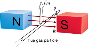
Questions SC 7, SC 8, and SC 9 relate to another experiment about cleaning flue gases from a power plant. A particle present in the flue gas, with a charge of –3.2 × 10⁻¹⁷ C, enters a region with a magnetic field strength of 2.5 × 10⁻² T. The magnitude of the particle's velocity was 12.0 m/s. The following diagram illustrates the details. Use this information to answer SC 7 to SC 9.
SC 7. Determine the direction of the magnetic force acting on the particle once it enters the magnetic field.
SC 8. In addition to the magnetic force, the force of gravity also acts on the particle. Under the right conditions, the effect of the magnetic force could be balanced by the force of gravity, allowing the particle to pass through the magnetic field undeflected. Draw a free-body diagram to illustrate the forces that would act on the particle in this case.
SC 9. Determine the necessary mass of the flue gas particle in order for it to pass through the magnetic field undeflected. Remember to use the GRASP method for solving problems.
Self-Check Answers
Contact your teacher if your answers vary significantly from the answers provided here.
SC 6.
Required
The acceleration of the proton.
Analysis and Solution
Find the force acting on the proton.
Fm = qvB
Fm = (1.60 × 10⁻¹⁹ C)(9.00 × 10⁴ m/s)(3.00 × 10–1 T)
Fm = 4.32 × 10⁻¹⁵ N [downwards]
Find the acceleration of the proton.
Paraphrase
The acceleration of the proton is 2.59 × 10² m/s2 [downwards, into the page]
SC 7.
SC 8.
SC 9.
Given
Required
the mass of the flue gas particle, m
Analysis and Solution
The gravitational force acting on the flue gas particle has a magnitude of ![]() and is directed downward. The magetic force acting on the glue gas particle has a magnitude of
and is directed downward. The magetic force acting on the glue gas particle has a magnitude of ![]() and is directed upward.
and is directed upward.
![]()
Since the forces balance, ![]() . Therefore,
. Therefore,
Paraphrase
The mass of the flue gas particle is 9.8 × 10⁻¹⁹ kg.
In 1897 Sir Joseph John Thomson (1856–1940) conducted an original study of cathode rays that resulted in the discovery of the electron. He was awarded the Nobel Prize in 1906 “in recognition of the great merits of his theoretical and experimental investigations on the conduction of electricity by gases.”
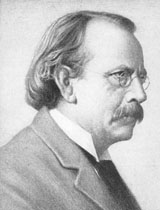
The following quote is taken from his Nobel Lecture on Physics on December 11, 1906:
In this lecture I wish to give an account of some investigations which have led to the conclusion that the carriers of negative electricity are bodies, which I have called corpuscles, having a mass very much smaller than that of the atom of any known element, and are of the same character from whatever source the negative electricity may be derived.
The first place in which corpuscles were detected was a highly exhausted tube through which an electric discharge was passing
.
Nobel Lectures: Physics, 1901–1921 (Amsterdam: Elsevier, 1967)
 Discuss
In his lecture Thomson continued to describe a series of experiments he had conducted on cathode rays. In one experiment he subjected the cathode ray to an external magnetic field to verify that the cathode ray consisted of nothing other than a stream of negative charges. Then he verified this in a second experiment where he successfully observed the cathode ray being deflected by an electric field—in a direction consistent with a negative charge. This had not been observed previously, and Thomson correctly assumed that this was due to leftover gases that could not be evacuated from the cathode ray tube due to imperfections in the equipment. Thomson’s equipment was able to achieve a greater vacuum than previous attempts.
In the third experiment Thomson measured the charge-to-mass ratio of the electron (which he described as a corpuscle).
D 1. Research Thomson’s work on the charge-to-mass ratio and answer the following:
-
If both an electric field and a magnetic field exert a force on a moving electron, could they be arranged in such a manner that each force cancels the other out, allowing the electron to pass through a CRT without being deflected? Sketch the orientation of the electric and magnetic fields to show that an electron travelling west could pass through each field simultaneously without being deflected. Label your diagram.
-
In order for an electron to pass through both the electric and magnetic fields without being deflected, the magnetic force (
 ) must be identical in magnitude to the electric force (
 ). Derive an expression for the velocity of the electron when these two forces are equal to one another.
-
If the electric field is turned off, what kind of motion will result from the application of only the magnetic field?
-
If the magnetic force (
 ) is an inward force (
 ) when acting alone, determine an expression for the charge-to-mass ratio of an electron (q/m) by first equating Fm and Fin.
-
Why was determining the charge-to-mass ratio of an electron considered important?
D 2. Post your responses to the discussion area for your class. Read the responses of at least two other students.
Module 4: Lesson 2 Assignment
Remember to submit the answers to D 3 to your teacher as part of your Module 4: Lesson 2 Assignment.
D 3. Revise your responses to D 1 and include comments on what you learned from reading other students’ responses.
Discussion Scoring Guide
Principles involved: Thomson’s charge-to-mass ratio experiment |
||||
Criteria |
Level 1 |
Level 2 |
Level 3 |
Level 4 |
Knowledge |
||||
| Demonstrates understanding of the situation, physics principles and technology, and their connections. | Demonstrates a vague and sometimes incorrect understanding of the physics principles involved. Obvious irrelevant or missing information. |
Demonstrates a basic understanding of the physics principles involved. May exhibit minor mistakes or vague information or application to the situation. |
Demonstrates a good understanding of the physics principles involved and applies them properly to the given situation. All necessary information is given. |
Demonstrates a superior understanding of the physics principles involved and their application to the situation. All applications are considered in detail. |
Reflection |
||||
The post shows reflection on one’s own and other students’ work. Contributes to the group discussion. |
Does not make an effort to participate. Seems indifferent to discussion. |
Occasionally makes meaningful reflections on the group’s efforts or discussions. Marginal effort is shown to become involved with the group or discussion. |
Frequently makes meaningful reflections on the group’s efforts and presents relevant viewpoints for consideration by the group. Interacts freely with group members. |
Regularly attempts to motivate the group discussion and delve deeper into concepts. Interacts freely and encourages all group members. |
Content and presentation of discussion summary |
||||
The information is logically arranged in a clear and concise manner. |
The information is poorly organized with many concepts implied. Irrelevant or rambling sentences make reading difficult. |
The information is somewhat organized with implied concepts. Excessive words or awkward sentences are used, which hinder reading. |
The information is well-organized and logically arranged. All concepts are explicitly explained. There are a few awkward but understandable sentences. |
The information is well-organized and very easy to understand. Well-worded sentences make reading pleasurable. |
1.14. Page 6
Module 4—Magnetic and Electric Fields in Nature and Technology
 Reflect and Connect

Image courtesy NASA
In the photograph, the aurora australis is seen in a distinctly circular pattern as it appears from space over Antarctica. The same pattern is observed over the arctic region. The circular pattern is related to the fact that the magnetic field exits and enters Earth near the geographical poles. These regions have a significant magnetic field passing vertically through the ionosphere. The magnetic field at these locations is also perpendicular to the motion of the charged particles in the solar wind.
 Watch and Listen
Watch the video Lorentz Force to see how Earth’s magnetic field exerts a magnetic force on charged particles to create the aurora.

© Palto/shutterstock
Reflect and Connect
The cathode ray tube played a very important role in the process of scientific discovery. It was instrumental in determining the charge-to-mass ratio of an electron and, ultimately, the mass of an electron. It also continues to be used for the demonstration of electromagnetism, revealing the relationship between magnetism and electricity.
But it is much more than that. It is a perfect example of scientific knowledge leading to the development of new technologies. After the work of Thomson, the CRT went on to be used in all kinds of applications. Most notable is the tube TV and computer monitor.
Save your responses to the following questions in your course folder.
RC 1. Explain how the television tube uses CRT technology to produce a moving colour picture.
RC 2. Describe the role of the electron gun and the magnetic field in tube televisions and explain why television sets don’t operate on batteries.
RC 3. Describe why cathode ray technology is destined to be a thing of the past.
 Module 4: Lesson 2 Assignment
Remember to submit the Module 4: Lesson 2 Assignment to your teacher.
1.15. Page 7
Module 4—Magnetic and Electric Fields in Nature and Technology
 Lesson Summary
In this lesson you focused on the following essential questions:
-
How is moving charge affected by a magnetic field?
-
Which variables determine the magnitude of the magnetic force?
-
How is the direction of the magnetic force determined?
When a charged particle moves perpendicularly to an external magnetic field, it exhibits uniform circular motion. The inward force is a magnetic force that is proportional to the product of the particle’s speed (perpendicular to the magnetic field), the magnitude of the particle’s charge, and the strength of the magnetic field in which it moves. Expressed mathematically it is
![]()
When the charged particle is moving at right angles to a magnetic field, the force exerted on the particle by the field is perpendicular to both the particle's velocity and the magnetic field. Therefore, to predict the direction of the magnetic force, you only need to know the direction of the particle’s velocity and the direction of the magnetic field.
The direction of the force acting on a negative particle can be determined by the left-hand rule for deflection. The direction of the force exerted on a positively charged particle moving in a magnetic field can be visualized by the right-hand rule for deflection.
A combination of the equation above and the appropriate hand rule can be used to determine the magnitude and direction of the magnetic force acting on any moving charged particle.
1.16. Lesson 3
Module 4—Magnetic and Electric Fields in Nature and Technology
Lesson 3—Electromagnetic Induction
 Get Focused
In Lesson 2 you learned that a charged particle, such as an electron, is deflected by an external magnetic field when it travels perpendicularly to that field. Suppose the electrons are “contained” within a conductor, such as a copper wire. If a copper wire is placed in an external magnetic field such that the electrons within it travel perpendicular to the field, will a magnetic force act on the electrons pushing them along the copper wire?
To see how this would work, view the DC Generator animation.
Would such a process work in reverse? That is, can you create a force on a conductor by forcing a current through it? Is this how it is used by an electric motor? What is the difference between an electric motor and a generator?
 Watch and Listen
Questions relating to magnetic and electric fields gained new significance after Ørsted discovered the magnetic field surrounding a current-carrying conductor. The work of Michael Faraday would build on these discoveries and lead to the invention of the world’s first electric motor based on an understanding of electromagnetic induction. Watch the video Faraday’s Discovery of Electromagnetic Induction to see an overview of Michael Faraday’s work, including a re-creation of the first electric motor.
Faraday’s work was based on the following fundamental question:
-
If an electric current produces a magnetic field, could a magnetic field be used to produce an electric current?
In Lesson 3 you will explore electromagnetic induction.
In this lesson you will answer the following essential questions:
-
What is the nature of the magnetic force acting on a current-carrying conductor in an external magnetic field?
-
How are magnetic forces used in a direct current motor?
-
How is a current produced by an electric generator?
 Module 4: Lesson 3 Assignment
Your teacher-marked Module 4: Lesson 3 Assignment requires you to submit a response to the following questions:
- Assignment—A 1, A 2, A 3, and A 4
- Lab—LAB 1, LAB 2, LAB 3, LAB 4, LAB 5, and LAB 6
- Discuss—D 3
The other questions in this lesson are not marked by the teacher; however, you should still answer these questions. The Self-Check and Try This questions are placed in this lesson to help you review important information and build key concepts that may be applied in future lessons.
After a discussion with your teacher, you must decide what to do with the questions that are not part of your assignment. You should record the answers to all the questions in this lesson and place those answers in your course folder.
1.17. Page 2
Module 4—Magnetic and Electric Fields in Nature and Technology
 Explore
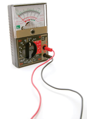
© Luis Fernando Curci Chavier/shutterstock
What is an electric current? In earlier science courses you learned that an electric current is defined by the collective movement of many, many charges. The photograph to the right shows a multi-meter, a device for displaying data related to electric current and voltage in a variety of ways. Many charges make up the electric current that flows through it. The current, or amount of charge that flows past a fixed point in a one-second interval, is displayed in amperes (A). The unit of electric current is named for André-Marie Ampère (1775–1836), a French scientist who contributed extensively to our understanding of the relationship between current and magnetic force.
electric current: the amount of charge, in coulombs, that passes a fixed point in a conductor in a one-second interval
Electric current expressed as an equation is as follows:
![]()
| Quantity | Symbol |
SI Unit |
electric current |
I |
ampere (A) |
charge of the particle |
q |
coulombs (C) |
interval |
t |
seconds (s) |
The SI unit of electric current is the ampere (A). One ampere of current is equivalent to one coulomb of charge passing a fixed point in a conductor in a one-second interval, 1 A = 1 C/s.
 Read
Read
Read “Electric Current” on page 602 of the textbook.
 Try This
TR 1.
-
Complete “Practice Problems” 1 and 2 on page 603 of the textbook.
-
In “Practice Problem” 2, how many electrons would have passed through the appliance in the 10-second interval?
 Module 4: Lesson 3 Assignment
Remember to submit the answers to A 1 to your teacher as part of your Module 4: Lesson 3 Assignment.
A 1. A compact fluorescent light bulb draws a current of 0.10 A for one hour.
- How much charge flows through the bulb in one hour?
- How many electrons flow through the light bulb in the hour? Remember the charge of one electron is the elementary charge on your physics data sheet.
Magnetic Force Direction
Recall from Lesson 2 that a moving charge induces a magnetic field and that when this magnetic field encounters an external magnetic field, the two fields will interact and cause the moving charge to experience a magnetic force (both magnitude and direction).
The hand rule used to predict the direction of the magnetic force acting on a charged particle in Lesson 2 can be used in a similar way to predict the direction of magnetic force acting on a current-carrying wire.
 Watch and Listen
Complete the tutorial Force on a Wire. It demonstrates how the hand rule is applied to determine the direction of the magnetic force that acts on a perpendicular current-carrying conductor in a magnetic field.
Left-hand Rule for Magnetic Force
The direction of the force exerted on a current-carrying conductor perpendicular to a magnetic field can be visualized by means of the left-hand rule illustrated in Figure 1. (There are several hand rules for this purpose. The following is only one suggestion.)

Figure 1
Hold your left hand flat with outstretched fingers in the direction of the magnetic field (![]() ) and with the thumb pointing off to one side in the direction of the negative current flow. The palm of your hand will then be pointing in the direction of the magnetic force (
) and with the thumb pointing off to one side in the direction of the negative current flow. The palm of your hand will then be pointing in the direction of the magnetic force (![]() ) that acts on the conductor.
) that acts on the conductor.
Read
Read “Left-hand Rule for Magnetic Force” on page 604 of the textbook for a summary of this hand rule. To further your understanding, view the animation Left-hand Rule for Magnetic Force.
Magnetic Force Magnitude
By combining the equation that describes the magnetic force acting on a moving, charged particle with the definition of electric current, it is possible to determine the size of the magnetic force acting on a current-carrying conductor (assuming the current direction is perpendicular to the magnetic field).
magnetic force on a charged particle
|
current
|
Combining both equations and treating the velocity in terms of units gives an equation that describes the size of the magnetic force acting on a current (I) carrying conductor of specific length (l), which is perpendicular to a magnetic field (B).
|
|
Expressed as an equation, ![]() .
.
Magnetic Force: The deflecting magnetic force acting on a current-carrying conductor is proportional to the product of the conductor’s length in the field and the current it carries perpendicular to the magnetic field at its location.
Expressed as an equation,
![]()
| Quantity | Symbol |
SI Unit |
magnetic force |
F |
newton (N) |
current |
I |
ampere (A) |
length of conductor |
l |
metres (m) |
strength of the magnetic field |
B |
tesla (T) |
In cases where only a component of the current and/or magnetic field are perpendicular, only the components that are perpendicular are used to calculate the size of the magnetic force.
Example Problem 1.
Determine the magnitude and direction of the magnetic force acting on a 0.500 m long conductor that carries a 2.00 A e– flow current west through a 3.50 × 10⁻¹ T magnetic field that is directed north.
Given
Magnitude
Fm = IlB
Fm = (2.00 A)(0.500 m)(3.50 × 10⁻¹ T)
Fm = 3.50 × 10⁻¹ N
Direction
According to the left-hand rule for negative charges, the force is upward.
Paraphrase
The magnetic force acting on the wire is 3.50 × 10⁻¹ N [up].
1.18. Page 3
Module 4—Magnetic and Electric Fields in Nature and Technology
 Try This
Before you answer TR 2, watch Quicklab 12-4 to see a demonstration of a current-carrying conductor in a uniform magnetic field.
TR 2. Answer “QuickLab” questions 1 to 3 on page 606 of the textbook.
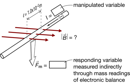
Example Problem 2.
The answer to “QuickLab” question 4 on page 606 of the textbook is provided below.
Apparatus
The following schematic gives an overview of the key principles that the experiment will use.
Materials Required
-
magnets to provide the magnetic field
-
some way to measure the force—an electronic balance perhaps
-
a variable source of current
-
a straight conductor and some way to insulate it
-
connecting wires from the straight conductor to the current source
The following diagram shows one possible set up.
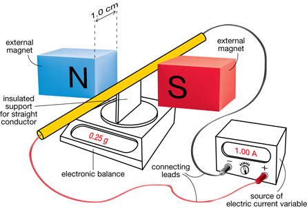
Procedure
-
Begin by conducting a safety audit. Exercise caution, given that current values will range from 1.0 A to 5.0 A.
-
Decide which way to connect the leads to the straight conductor: one way causes the magnetic force to be directed straight down (resulting in an increased reading on the balance, the desired scenario) and the other way causes the magnetic force to be directed straight up (resulting in a decreased reading on the balance).
-
"Zero" the balance when electric current reads zero amperes.
-
Begin the data collection. A table like the one following could be used to record the needed information:
Electric Current |
Mass |
Corresponding Force |
0 |
0 |
0 |
1.0 |
|
|
2.0 |
|
|
3.0 |
|
|
4.0 |
|
|
5.0 |
|
|
- Adjust the knob on the source of electric current to increase the value of the electric current flowing through the wire. Increases such as those suggested in the data table could be used for ease of analysis. The corresponding value on the electronic balance would be recorded in each case.
- Begin the data analysis by calculating the corresponding force for each current level (Fm = m × 9.81 m/s2). The following chart shows one set of measurements and the results of the calculations.
Electric Current |
Mass |
Corresponding Force |
0 |
0 |
0 |
1.0 |
0.25 |
2.5 × 10⁻³ |
2.0 |
0.51 |
5.0 × 10⁻³ |
3.0 |
0.74 |
7.3 × 10⁻³ |
4.0 |
1.03 |
10.1 × 10⁻³ |
5.0 |
1.27 |
12.5 × 10⁻³ |
-
Graph the data.
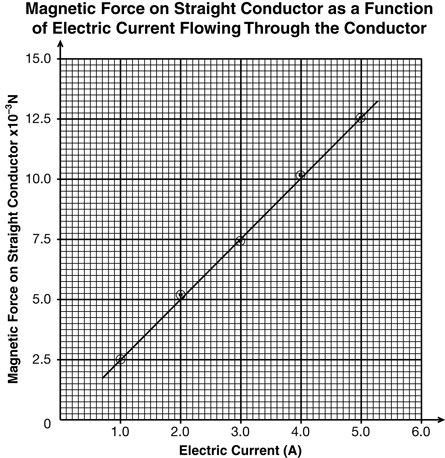
- Find the slope and use its value to calculate the strength of the magnetic field in the region between the two magnets.
From the graph
From the formula

Conclusion
The strength of the magnetic field is 0.25 T.
1.19. Page 4
Module 4—Magnetic and Electric Fields in Nature and Technology
 Try This
TR 3. Complete “Practice Problems” 1 and 2 on page 605 of the textbook.
 Module 4: Lesson 3 Assignment
Remember to submit the answer to A 2 to your teacher as part of your Module 4: Lesson 3 Assignment.
A 2. A motor uses a coil of wire in a magnetic field to generate force. The motor draws a current of 9.50 A through the coil of wire and has a magnetic field of 1.75 T. If the motor is designed to generate 800 N, how long is the wire in the coil, assuming that all of the wire creates force?

© 2005 HyperPhysics by Rod Nave, Georgia State University. Used with permission.
The Direct Current Electrical Motor
The magnetic force acting on a conductor can be used to rotate a loop of wire. In this image, the electrons making up the current travel around the loop of wire. Since the direction of current is opposite on either side of the loop, so too is the direction of the magnetic force, as predicted by the hand rule. The sum of these two forces causes the loop of wire to spin. Use the left-hand rule on each side of the conductor to prove to yourself that this is the case.
A split ring commutator and a set of brushes reverse the current direction in the wire every half turn, ensuring the orientation of the magnetic force is always up on one side and down on the other. The magnetic force in this application is known as the motor effect.
Module 4: Lesson 3 Assignment
Remember to submit the answers to A 3 to your teacher as part of your Module 4: Lesson 3 Assignment.
A 3. What would happen to the direction of the magnetic force if the loop of wire were to undergo one half-turn without reversing the direction of the current in the loop?
 Watch and Listen
Watch an animation of a simple direct current electric motor. Note that the animation uses conventional current, which is the movement of positives. You will have to use the right-hand rule to find the direction of the magnetic force. The black arrows show the direction of the magnetic force.
Note that when the coil is perpendicular to the magnetic field, the connection to the DC voltage is broken; the black line on the commutator is a gap that breaks the electrical connection to the battery. The boxes are brushes that create that connection when they touch the metal part of the commutator.
When this connection is broken, there is no current flowing and no magnetic force.
 Self-Check
SC 1. How does the direct current electric motor keep moving when the connection is broken and there is no current flowing and no magnetic force?
Self-Check Answers
Contact your teacher if your answer varies significantly from the answer provided here.
SC 1. The coil’s momentum moves it past the gap where the current has switched directions, as previously described.
Watch and Listen
To understand the meaning of the statement “the current changes direction,” focus on just one side of the loop of wire during a full rotation. Refer to the simulation DC Motor Operation for a more detailed schematic of the DC motor.
 Read
Read
Read “The Electric Motor” on pages 608–609 of the textbook.
Self-Check
SC 2. Answer the “Concept Check” question on page 609. Hint: The answer is in the DC Motor Operation simulation you looked.
Self-Check Answers
Contact your teacher if your answer varies significantly from the answer provided here.
SC 2. Reverse the battery / voltage source.
The Generator Effect
Symmetry in nature has allowed scientists to make important discoveries. For example, the similarities between electric and gravitational fields led Coulomb to conclude that the same mathematical relationships described by Newton’s gravitational laws could be applied to electrostatic interactions as well. In another instance of symmetry, Michael Faraday (1791–1867) and Joseph Henry (1797–1878) understood that if electricity could produce magnetism, as Ørsted’s compass proved, then magnetism should be able to produce electricity. In other words, if moving charges produce a magnetic field, then a magnetic field should also be able to produce moving charges (current). The process should work both ways. Experiments conducted in 1831 by Faraday and Henry supported this theory.
Read
generator effect or electromagnetic induction: the production of electrical current by the relative motion of a conductor in a magnetic field
Faraday and Henry concluded that when a piece of conducting wire moves perpendicularly through a magnetic field, a current is induced. This is known as the generator effect or electromagnetic induction.
Read “The Generator Effect” and “Faraday’s and Henry’s Discoveries” on pages 609–611 of the textbook. Look over “Inquiry Lab” on page 612 of your textbook.
1.20. Page 5
Module 4—Magnetic and Electric Fields in Nature and Technology
Module 4: Lesson 3 Lab—The Generator Effect
In this lab you will investigate how a changing magnetic field can induce an electrical current in a conductor. In order for the generator effect to occur, there must be relative motion between an external magnetic field, such as that produced by a bar magnet, and a conducting wire. By forming the conducting wire into a loop, the generator effect can be amplified and observed using a galvanometer (to measure the current) or a voltage meter (to measure the charge separation as a result of the current).
Problem
What factors increase the current produced in a generator?
Materials
“Faraday’s Electromagnetic Lab” simulation
Procedure
- Open “Faraday’s Electromagnetic Lab” simulation. Select the “Pickup Coil” tab at the top of the simulation window and select the voltage meter instead of the light bulb as the indicator.
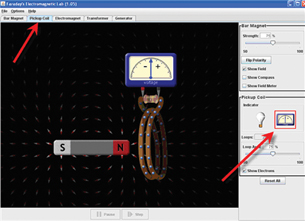
© PhET Interactive Simulations, University of Colorado. Some rights reserved.
- Move the bar magnet back and forth through the loop of wire, and observe the voltage meter. Answer Analysis question LAB 1.
- Switch the indicator back to the light bulb, and move the magnet through the coil. Try moving the magnet at different speeds. Then try moving the coil. Answer Analysis question LAB 2.
- Select the “Generator” tab at the top of the simulation window and turn the water tap on by sliding the lever as indicated below. Observe the magnitude and direction of the voltage as the magnet spins.
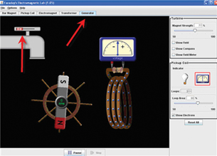
© PhET Interactive Simulations, University of Colorado. Some rights reserved.
- Adjust the magnetic strength and observe the magnitude of the voltage meter swing. Answer Analysis question LAB 3a.
- Adjust the water flow and observe the magnitude of the voltage meter swing. Answer Analysis question LAB 3b.
- Adjust the number of loops and observe the magnitude of the voltage meter swing. Answer Analysis question LAB 3c.
- Adjust the loop area and observe the magnitude of the voltage meter swing. Answer Analysis question LAB 3d.
Analysis
 Module 4: Lesson 3 Assignment
Remember to submit the answers to LAB 1 to LAB 6 to your teacher as part of your Module 4: Lesson 3 Assignment.
LAB 1. “Pickup” coil: how does the direction of the movement of the magnet affect the direction of the deflection on the voltage meter?
LAB 2. “Light bulb”: how does the speed of the magnet or coil affect the light?
LAB 3. “Generator”: describe how each of the following factors influences the magnitude of the deflection:
- strength of the magnetic field
- speed of the magnet passing the coil (adjusted by changing the water flow)
- the number of loops
- the loop area
LAB 4. Explain why the generator effect would occur in the same way if the wire were moved rather than the magnet.
Conclusions
LAB 5. Summarize the factors that determine the magnitude and direction of the induced current when there is relative motion between a magnetic field and a conductor.
Looking Ahead
LAB 6. Describe the change in the direction (sign) of the voltage as the magnet spins. Note that this “flip” in direction does not happen with a battery (direct current, or DC, voltage source). This generator, therefore, is not generating direct current! It is an AC (alternating current) generator.
 Self-Check
SC 3. Based on your results from the lab you just completed, which of the three coils in “Figure 12.37” in the “Inquiry Lab” would produce the most current?
Self-Check Answers
Contact your teacher if your answer varies significantly from the answer provided here.
SC 3. The larger loop would produce the most current.
 Module 4: Lesson 3 Lab—The Curious Relationship Between Motors and Generators
Lenz’s law: the direction of a magnetically induced current is oriented such that it produces a magnetic field, which opposes the motion causing it
Refer to the “Inquiry Lab” on page 616 of your textbook. Then watch the simulation 12–7 Inquiry Lab. According to the observations in the simulation, when a magnet falls through a metal pipe conductor, it generates an induced current in the conductor. The direction of this induced current produces its own magnetic field that “opposes” the motion of the falling magnet causing it. This slows down the magnet extending the time it takes to fall through the pipe. This process is known as Lenz’s law.
Example Problem 3. A bar magnet moves towards and then away from a solenoid connected to a galvanometer. In which direction is the induced current when the magnet approaches, and when it moves away from the solenoid?
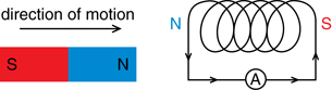
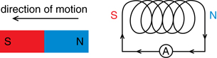
In the diagram, if the bar magnet moves towards the solenoid, the induced current (left to right through the ammeter) will be in a direction that produces a similar pole (north on the left of the solenoid), repelling the approaching magnet. If the bar magnet moves away, the induced current reverses direction (right to left through the ammeter), reversing the poles of the solenoid (south on the left of the solenoid) to attract the leaving magnet. You can observe this in the video clip on Faraday’s research into electromagnetic induction in the Watch and Listen activity below.
 Watch and Listen
The video Electromagnetic Induction will explain Faraday’s work on electromagnetic induction. If you have not completed Math 31, ignore the equations at the end of the video as they involve calculus and are beyond the scope of Physics 30.
Therefore, you can assign the magnetic poles of the solenoid based on Lenz’s law. Using the left-hand rule for solenoids, grasp the coil with your thumb pointing in the direction of the magnetic field within the coil (which is from the south pole to the north pole). Your fingers then wrap around the coil in the direction of electron flow.
Lenz’s law is a direct consequence of the conservation of energy. Consider the falling magnet in a conductor, which you saw in Inquiry Lab 12–7. If the induced current in the conductor, caused by the motion of the falling magnet, were orientated in such a way that it produced a magnetic field supporting the movement of the magnet, it would cause it to accelerate downward at a greater rate. That would increase the current in the conductor, which would lead to a further increase in the downward acceleration of the magnet, leading to an even greater induced current and magnetic field, producing greater accelerations, and so forth. This would mean that a magnet dropped into a metal pipe would accelerate like a bullet and shoot out of the lower end! A positive feedback loop such as this would be creating energy, violating the universal law of the conservation of energy.
 Read
Read
Read “Lenz’s Law” on pages 617–619 of the textbook.
Module 4: Lesson 3 Assignment
Remember to submit the answer to A 4 to your teacher as part of your Module 4: Lesson 3 Assignment.
A 4. Fill in the "?" with the missing information in each of the following diagrams. In the diagrams a magnet is either dropped down or pulled up through a cylinder encircled by a coil conductor. Remember that current is e- flow.
a. 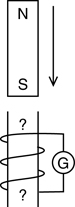 b.
b. 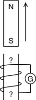 c.
c. 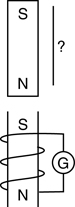 d.
d. 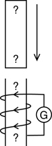 e.
e. 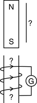 f.
f. 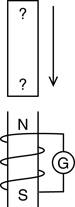

© Paul Laragy/shutterstock
 Discuss
D 1. Would two parallel wires carrying a current in opposite directions repel or attract one another? Include a diagram in your response. Refer to page 607 of your textbook to get started.
D 2. Post your response to the discussion area of your class. Read the postings of at least two other students.
Module 4: Lesson 3 Assignment
Remember to submit the answer to D 3 to your teacher as part of your Module 4: Lesson 3 Assignment.
D 3. Based on the other students’ responses, revise your answer to D 1 and comment on the other students’ answers.
Discussion Scoring Guide
| Principles involved: magnetic field around current-carrying conductors, magnetic forces | ||||
Criteria |
Level 1 |
Level 2 |
Level 3 |
Level 4 |
Knowledge |
||||
Demonstrates understanding of the situation, physics principles and technology, and their connections. |
Demonstrates a vague and sometimes incorrect understanding of the physics principles involved. Obvious irrelevant or missing information. |
Demonstrates a basic understanding of the physics principles involved. May exhibit minor mistakes or vague information or application to the situation. |
Demonstrates a good understanding of the physics principles involved and applies them properly to the given situation. All necessary information is given. |
Demonstrates a superior understanding of the physics principles involved and their application to the situation. All applications are considered in detail. |
Reflection |
||||
The post shows reflection on one’s own and other students’ work. Contributes to the group discussion. |
Does not make an effort to participate. Seems indifferent to discussion. |
Occasionally makes meaningful reflections on the group’s efforts or discussions. Marginal effort is shown to become involved with the group or discussion. |
Frequently makes meaningful reflections on the group’s efforts and presents relevant viewpoints for consideration by the group. Interacts freely with group members. |
Regularly attempts to motivate the group discussion and delve deeper into concepts. Interacts freely and encourages all group members. |
Content and presentation of discussion summary |
||||
The information is logically arranged in a clear and concise manner. |
The information is poorly organized with many concepts implied. Irrelevant or rambling sentences make reading difficult. |
The information is somewhat organized with implied concepts. Excessive words or awkward sentences are used, which hinder reading. |
The information is well-organized and logically arranged. All concepts are explicitly explained. There are a few awkward but understandable sentences. |
The information is well-organized and very easy to understand. Well-worded sentences make reading pleasurable. |
1.21. Page 6
Module 4—Magnetic and Electric Fields in Nature and Technology
 Reflect and Connect

© sculpies/shutterstock
Is a motor a generator? Is a generator a motor? They are, in fact, the same thing. Consider the electric motor fan and the wind turbine. In the fan motor, the movement of electrons through a conductor located in a non-parallel magnetic field generates a magnetic force causing the rotational motion of the fan. In a wind turbine, as shown in the photograph on the right, an external force (wind) is used to push a conductor through a magnetic field, inducing a current flow in the conductor. Connecting the motor and generator with a conducting wire (recall the transmission lines from Module 3) allows the energy captured at the wind turbine to be delivered and used by the electric fan.
Since the motor and generator are essentially the same thing, both depend on similar components:
- an external magnetic field
- a conductor, which is driven by an external force in a generator or a magnetic force in a motor
- a commutator for controlling the current direction in the conductor, relative to the external magnetic field
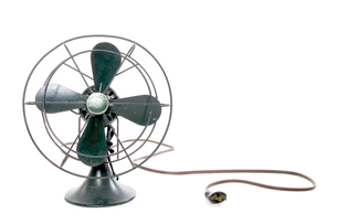
© Michael Drager/shutterstock
 Module 4: Lesson 3 Assignment
Remember to submit the Module 4: Lesson 3 Assignment to your teacher.
1.22. Page 7
Module 4—Magnetic and Electric Fields in Nature and Technology
 Lesson Summary
In this lesson you focused on the following essential questions:
- What is the nature of the magnetic force acting on a current-carrying conductor in an external magnetic field?
- How are magnetic forces used in a direct current motor?
- How is a current produced by an electric generator?
In a similar way to that of a charge moving perpendicularly to a magnetic field, a magnetic force acts on a current-carrying conductor located perpendicularly in a magnetic field. Electric current is measured in amperes (the amount of charge, in coulombs, passing a fixed point in a conductor each second). Mathematically, it is expressed as
![]()
The direction and magnitude of the magnetic force acting on a current-carrying conductor is determined, respectively, by hand rules and the product of the current, length of wire in the field, and strength of the magnetic field. Mathematically, it is expressed as
![]()
This equation describes the magnitude of the motor effect, since the force can be used to rotate a conducting loop in an external magnetic field.
The direct current electric motor is essentially an electric generator in reverse. When a conductor is forced through a non-parallel magnetic field, a current is induced in the wire. This is known as the generator effect. Furthermore, the direction of the induced current is such that it produces a magnetic field, which opposes the motion causing it. This is known as Lenz’s law. Taken together, the motor effect and the generator effect are linked by the interaction of electric and magnetic fields.
Lesson Glossary
electric current: the amount of charge, in coulombs, that passes a fixed point in a conductor in a one-second interval
The unit of current is the ampere, equivalent to one coulomb of charge passing a fixed point in a conductor in a one-second interval.
generator effect or electromagnetic induction: the production of electrical current by the relative motion of a conductor in a magnetic field
Lenz’s law: the direction of a magnetically induced current is orientated such that it produces a magnetic field that opposes the motion causing it
motor effect: the magnetic force produced when a current-carrying conductor is located in a perpendicular magnetic field
1.23. Module Summary/Assessment
Module 4—Magnetic and Electric Fields in Nature and Technology
 Module Summary
This module was all about how the properties of electric and magnetic fields are applied in numerous devices.
In Lesson 1 you explored magnetic fields. You learned that the magnetic field surrounding a bar magnet is from north to south and that when a compass is placed in a magnetic field the north pole of the compass needle points in the same direction as the field.

You were also introduced to the hand rules. You can use hand rules to determine the direction of magnetic fields surrounding a current-carrying wire or through a cold of wire (solenoid).
Lastly, you learned that the connection between moving charge and the production of magnetic fields is the first step in understanding electromagnetism observed in nature and used in modern technologies such as electrical generators and motors.
In Lesson 2 you discovered that when a charged particle moves in an external magnetic field, it exhibits uniform circular motion. The inward force is a magnetic force that is proportional to the product of the particle’s speed (perpendicular to the magnetic field) and charge, and the strength of the magnetic field in which it moves. Expressed mathematically it is
![]()
You also learned how to predict the direction of the magnetic force using hand rules when you know the direction of the particle’s velocity and the direction of the magnetic field.
In Lesson 3 you learned that in a perpendicular magnetic field, a magnetic force is generated when a current-carrying conductor is located in a perpendicular magnetic field, which is similar to that of a moving charge.
You will investigate how the direction and magnitude of the magnetic force acting on a current-carrying conductor is determined, respectively, by hand rules and the product of the current, length of wire, and strength of the perpendicular magnetic field. Expressed mathematically it is
![]()
You also discovered why the direct current electric motor is essentially an electric generator in reverse. When a conductor is forced through a perpendicular magnetic field, a current is induced in the wire. This is known as the generator effect. Furthermore, the direction of the induced current is such that it produces a magnetic field that opposes the motion causing it. This is known as Lenz’s law.
Lastly, you explored how the motor effect and the generator effect are linked by the interaction of electric and magnetic fields.
All of the concepts presented in Module 4, along with the ones you learned in Module 3, will help you understand the nature and function of electrical generation and consumption.
 Module Assessment
Question 1
Use the following information to answer this graphing question.
A student used the apparatus shown below to measure the radius of the curvature of the path of electrons as they pass through a magnetic field that is perpendicular to their path. This experimental design has the voltage as the manipulated variable, the speed calculated from the voltage, and the radius as the responding variable.
Accelerating Potential Difference (V) |
Speed (m/s) |
Radius (m) |
20.0 |
2.65 × 10⁶ |
7.2 × 10⁻² |
40.0 |
3.75 × 10⁶ |
9.1 × 10⁻² |
60.0 |
4.59 × 10⁶ |
11.0 × 10⁻² |
80.0 |
5.30 × 10⁶ |
12.8 × 10⁻² |
100.0 |
5.93 × 10⁶ |
14.1 × 10⁻² |
120.0 |
6.49 × 10⁶ |
16.3 × 10⁻² |
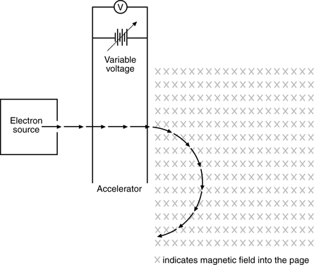
a. Plot the graph of radius as a function of speed, and construct a best-fit line.
b. Using the slope or other appropriate averaging technique, determine the strength of the magnetic field.
c. Derive the equation that would allow you to calculate the speed of the electrons from the accelerating potential.
Graphing
(5 marks)
Scoring Guides for Graphing Skill-Based Questions––Mathematical Treatment
Score |
Description |
5 |
Note: One minor error may be present.* |
4 |
or
|
3 |
|
2 |
|
1 |
|
0 |
|
*Minor errors include
- misreading a data value while interpolating or extrapolating up to one-half grid off
- stating the final answer with incorrect (but not disrespectful) units
- stating the final answer with incorrect (but not disrespectful) significant digits
- missing one of several different formulas
**Implicit treatment means
- substituting appropriate values into a formula from the data sheets without stating the formula
- starting with memorized, derived formulas not given on the equations sheet
- substituting the value from one calculation into a second formula without communicating that the physics quantity in the two formulas is the same
***Major errors include
- using off-line points (Most often, this is calculating the slope using data points that are not on a linear line of best fit.)
- using a single data point ratio as the slope
- missing powers of 10 in interpolating or extrapolating
Question 2
Use the following information to answer this holistic question.
A teacher demonstrates how magnets can be used to create a current. The teacher attaches a coil of wire to a retort stand. The ends of the coil are attached to an ammeter. The teacher then drops a strong, rare, earth magnet through the coil. The students observe the movement of the ammeter and graph the results.
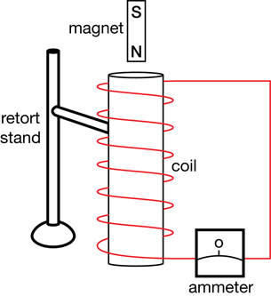
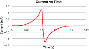
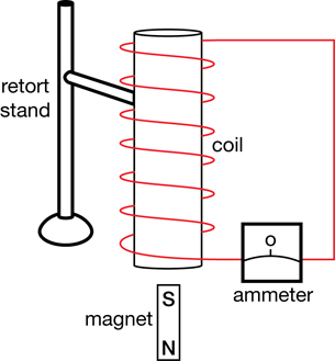
Analyze the students’ observations by
- describing the energy conversions (kinetic energy, gravitational potential energy, and electric energy) that occur in the magnet and coil system
- labelling the north and south magnetic poles induced in the coil in each picture (Justify your labels.)
- identifying and explaining the direction of the current as shown on the graph
Holistic Scoring Guide
Major Concepts: Magnetic and electric fields |
|
Score |
Description |
5 |
The nature of a response that will receive a score of 5 has the following characteristics:
Note: The response may contain minor errors or have minor omissions. |
4 |
The nature of a response that will receive a score of 4 has the following characteristics:
Note: The response is mostly complete and mostly correct, although it may contain errors or have omissions, and contains some application of physics principles. |
3 |
The nature of a response that will receive a score of 3 has the following characteristics:
|
2 |
The nature of a response that will receive a score of 2 has the following characteristic:
|
1 |
The nature of a response that will receive a score of 1 has the following characteristic:
|
0 |
The student provides a solution that is invalid for the question. |
* Explicit means the response is clearly stated; the marker does not have to interpret.
** Implicit (implied) means the response is not clearly stated; the marker must interpret.
For example,
Explicit: An electron has a negative charge while a proton has a positive charge.
The answer is clear with no possible misinterpretation.
Implicit: An electron has a negative charge while a proton does not.
The answer is not clear because the marker does not know whether a proton is neutral or positively charged. There is more than one possible way to interpret the answer.
1.24. Module Glossary
Module 4—Magnetic and Electric Fields in Nature and Technology
Module Glossary
domain: the region of a material in which the magnetic fields of most of the atoms are aligned
electric current: the amount of charge, in coulombs, that passes a fixed point in a conductor in a one-second interval
The unit of current is the ampere, equivalent to one coulomb of charge passing a fixed point in a conductor in a one-second interval.
ferromagnetic material: a metal with adjacent atoms having electron movement that, taken together, form a small region with an intense magnetic field
generator effect or electromagnetic induction: the production of electrical current by the relative motion of a conductor in a magnetic field
Lenz’s law: the direction of a magnetically induced current is orientated such that it produces a magnetic field that opposes the motion causing it
magnetic field: a three-dimensional region of magnetic influence surrounding a magnet in which other magnets or magnetic substances are affected by magnetic forces
magnetic flux: the number of magnetic field lines passing through a given area perpendicular to the field
motor effect: the magnetic force produced when a current-carrying conductor is located in a perpendicular magnetic field
solenoid: an electromagnet that operates a mechanical device by using the magnetic field produced by a current-carrying conductor wrapped into a coil
tesla: a unit of magnetic field strength (T) defined as one ![]() or one
or one ![]()