Module 3
| Site: | MoodleHUB.ca 🍁 |
| Course: | Physics 30 SS |
| Book: | Module 3 |
| Printed by: | Guest user |
| Date: | Wednesday, 17 December 2025, 12:22 AM |
Description
Created by IMSreader
Table of contents
- 1. Module 3
- 1.1. Big Picture
- 1.2. In this Module
- 1.3. Lesson 1
- 1.4. Page 2
- 1.5. Page 3
- 1.6. Page 4
- 1.7. Page 5
- 1.8. Page 6
- 1.9. Page 7
- 1.10. Lesson 2
- 1.11. Page 2
- 1.12. Page 3
- 1.13. Page 4
- 1.14. Page 5
- 1.15. Page 6
- 1.16. Page 7
- 1.17. Lesson 3
- 1.18. Page 2
- 1.19. Page 3
- 1.20. Page 4
- 1.21. Page 5
- 1.22. Page 6
- 1.23. Lesson 4
- 1.24. Page 2
- 1.25. Page 3
- 1.26. Page 4
- 1.27. Page 5
- 1.28. Page 6
- 1.29. Page 7
- 1.30. Lesson 5
- 1.31. Page 2
- 1.32. Page 3
- 1.33. Page 4
- 1.34. Page 5
- 1.35. Page 6
- 1.36. Page 7
- 1.37. Page 8
- 1.38. Page 9
- 1.39. Page 10
- 1.40. Page 11
- 1.41. Lesson 6
- 1.42. Page 2
- 1.43. Page 3
- 1.44. Page 4
- 1.45. Page 5
- 1.46. Page 6
- 1.47. Page 7
- 1.48. Module Summary/Assessment
- 1.49. Module Glossary
1. Module 3
Module 3—Electrical Phenomena
Module Introduction
In Module 3 you will explore electrical phenomena and the behaviour of electrical charges. You will see how an understanding of electricity was built up over time through experimentation. You will explore the similarities between electrical phenomena and gravity, and see how the equations for working with both are similar. You will also learn how to describe electrical phenomena and transmission using electric field theory.
1.1. Big Picture
Module 3—Electrical Phenomena
 Big Picture

© Monkey Business Images/shutterstock
Have you ever spent a summer’s day hiking in the mountains? If you have, you know it’s important to keep an eye on cloud formations so you can anticipate stormy weather. Anticipating bad weather is about more than keeping dry—late afternoon thunderstorms can be a real hazard in open areas at high elevations.
Even when precautions are taken, storm clouds can suddenly blow in from behind a nearby ridge, giving only minutes’ warning that a storm is approaching. In these circumstances, hikers are urged to avoid ridges and trees and to wait in as low a location as possible for the storm to pass. As the storm clouds pass overhead, if the hikers notice that their skin starts to tingle, their hair stands on end, and/or the ends of metal gear starts to hum and spark, then lightning may be about to strike. This is an example of static electricity. You will learn more about this in this module.
As you are working in Module 3, keep the following questions in mind:
- How is it that thunderclouds, kilometers overhead, can produce such dramatic effects on the ground below?
-
What is physically transferred between the cloud and the ground when lightning strikes?
-
How can the energy transfer in events like this be described?
 Module Assessment
Each lesson has a teacher-marked assignment, based on work completed in the lesson. In addition, you will be graded on your contributions to the Discuss section of each lesson.
You will also be asked to complete Self-Check or Try This questions, which you should place in your Physics 30 course folder. These are not formally assessed but are a valuable way to practise the concepts and skills of the lesson. These activities can provide you with reflective feedback on your understanding of the lesson work.
You will be marked for your lesson work on the following items:
-
Module 3: Lesson 1 Assignment
-
Module 3: Lesson 2 Assignment
-
Module 3: Lesson 3 Assignment
-
Module 3: Lesson 4 Assignment
- Module 3: Lesson 5 Assignment
- Module 3: Lesson 6 Assignment
At the end of the module you will complete a module assessment that consists of two Diploma Exam-style written-response questions. The first question will assess your knowledge of charge-to-mass ratios and the second question will assess your knowledge of electromagnetic induction. See the Module Assessment page for more information.
1.2. In this Module
Module 3—Electrical Phenomena
In This Module

© Jhaz Photography/shutterstock
Lesson 1—Electrostatics
In this lesson, you will explore static electricity, conductors, insulators, charge conservation, and the three methods of transferring charge.
You will investigate the following essential questions:
- Can the concepts that explain large-scale phenomena like lightning be explored using small-scale equipment like a Van de Graaff generator?
- How can these concepts explain what happens to charges within a cloud during a lightning strike?
Lesson 2—Investigating Coulomb’s Law
If charges can interact and exert forces on one another over great distances, how can the interaction of these charges be described? If the law of universal gravitation describes the force of attraction of one mass on another mass, then which law explains the force that acts on one charge due to another charge?
In this lesson you will explore the work of Charles Coulomb and learn how the results of his torsion balance experiments led to an equation describing the electrostatic force between two objects, now known as Coulomb’s law.
You will investigate the following essential questions:
- What is Coulomb’s law, and how was this law determined using the results of experiments?
- Can Coulomb’s law predict the effect of electrostatic force if the distance of separation increases by a known amount? What does the answer to this question suggest about lightning safety?
Lesson 3—Applying Coulomb’s Law
In this lesson you will apply Coulomb’s law to the exploration of both large-scale and extremely small-scale phenomena.
You will investigate the following essential questions:
- How much charge is transferred in a lightning strike, and how is this amount of charge measured?
- How can Coulomb’s law be applied to predict the net force acting on one point charge due to the presence of other point charges? How does this sort of analysis relate to the symmetry found in crystals?
Lesson 4—Electric Fields
In this lesson you will study electric fields and how to describe and analyze their effects.
You will investigate the following essential questions:
- What is an electric field, and how can an electric field be described and analyzed?
- What exactly is St. Elmo’s fire, and why does it occur at the end of tall pointed surfaces like lightning rods and ships’ masts?
Lesson 5—Electric Potential Energy
In this lesson you will study electric fields and how they lead to electric potential energy. You will learn that there are similarities with gravitational potential energy.
You will investigate the following essential questions:
- What is electric potential energy? How is it similar to gravitational potential energy?
- What is voltage? How is voltage calculated?
Lesson 6—The Motion of Charges in Uniform Electric Fields
In this lesson you will study the motion of charged particles in electric fields. You will compare this to motion in other fields you have previously studied.
You will investigate the following essential questions:
- How do charged particles move in a uniform electric field? How is this motion similar to a mass moving in a gravitational field?
- Is it possible to predict the velocity, acceleration, and displacement of charged particles moving in electric fields?
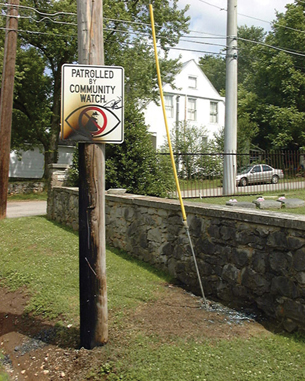
1.3. Lesson 1
Module 3—Electrical Phenomena
Lesson 1—Electrostatics
 Get Focused

© NOAA US Gov
This photograph shows a young woman at a lookout platform in a mountain park. Her brother was so surprised to see her hair standing on end that he took this photograph. Moments after the photograph was taken, lightning struck the platform, seriously injuring the woman and others on the platform.
What caused the woman’s hair to stand on end? How was this an indicator that lightning was about to strike? Is there a safe way to observe and analyze related phenomena in the lab?
In this lesson you will focus on answering the following essential questions:
- Can the concepts that explain large-scale phenomena like lightning be explored using small-scale equipment like a Van de Graaff generator?
- How can these concepts explain what happens to charges within a cloud during a lightning strike?
 Module 3 Lesson 1 Assignments
Your teacher-marked Module 3, Lesson 1 Assignment requires you to submit a response to the following questions:
- Assignment—A 1, A 2, A 3, and A 4
- Discuss—D 4
The other questions in this lesson are not marked by the teacher; however, you should still answer these questions. The Self-Check and Try This questions are placed in this lesson to help you review important information and build key concepts that may be applied in future lessons.
After a discussion with your teacher, you must decide what to do with the questions that are not part of your assignment. For example, you may decide to submit to your teacher the responses to Try This questions that are not marked. You should record the answers to all the questions in this lesson and place those answers in your course folder.
Required Materials and Equipment
For this lesson, you will need
- two spherical balloons (about 25 cm in diameter)
- 2 m of thread
- something made from wool (e.g., a piece of cloth, wool sweater, sock, tuque, or blanket)
1.4. Page 2
Module 3—Electrical Phenomena
 Explore

© Courtesy of COSI Columbus
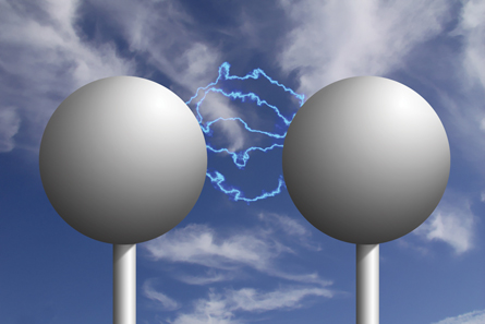
The effect observed in this photo is due to static electricity, as was the case in the photo of the woman in Get Focused. In this case it is produced by the machine the girl is touching—a Van de Graaff generator. It’s a powerful tool for studying static electricity. It can safely illustrate many of the key concepts that are involved in more complicated phenomena like lightning. You’re going to learn more about the nature of the electrical transmission that occurs in a lightning strike, starting with a Van de Graaff generator.
 Try This: Charging Objects Using a Van de Graaff Generator
Think about charging objects using a Van de Graaff generator as you answer these questions:
TR 1. What do you already know about static electricity?
TR 2. How would you explain a person’s hair standing on end when he or she touches a Van de Graaff generator?
In this activity you will have a chance to apply what you know as you explore a number of intriguing demonstrations.
Your initial explanations of these ideas will mark your starting point as you begin this module. Even if you aren’t sure, go ahead and hypothesize as you determine what’s going on.
Lab Choice
This activity can be done in two ways. If you have access to a supervised science lab equipped with the materials and equipment listed on page 511 of your textbook, use Method A. If you do not have access to these facilities, use Method B. Both methods will require you to refer to page 511 in your textbook.
Method A: Using a Supervised Science Lab
Follow the instructions described in the “QuickLab” on page 511 of your textbook.
Method B: Without a Supervised Science Lab
Open the Charging Objects Using a Van de Graaff Generator multimedia object. This multimedia object follows the instructions outlined in the “QuickLab” on page 511 of your textbook, so you’ll need your textbook too.
 Module 3: Lesson 1 Assignment
Remember to submit the answer to A 1 to your teacher as part of your assignment.
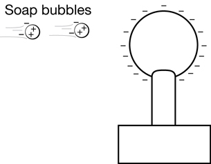
A 1. Record your observations and explanations for each of the following objects that interacted with the charged globe of the Van de Graaff generator:
- animal fur
- aluminum pie plates
- confetti
- soap bubbles
Charging a Balloon

You can produce your own electrostatic effects using two balloons, about 2 m of thread, and a wool sweater.
 Self-Check
SC 1. Inflate one of the balloons. Use about 1 m of thread to tie the balloon to a high point in a room away from any walls. A light fixture works well for this. Rub the balloon with the wool sweater; then bring the sweater close to the balloon but don’t let them touch. Record your observations.
SC 2. Inflate the second balloon and tie it to the same spot as the first balloon. Ensure that the centres of the balloons are at the same height above the floor. Rub each balloon vigorously with the wool sweater, and then observe what happens to each balloon. Record your observations.
SC 3. Apply Newton’s third law to the electrostatic forces that act on each balloon.
SC 4. Draw a free-body diagram to illustrate the forces acting on each balloon.
Self-Check Answers
SC 1. The balloon is attracted to the wool sweater. It is difficult to have the balloon not touch the wool sweater because the closer the balloon gets to the sweater, the stronger the attraction to the sweater.
SC 2. Each balloon repels the other. This force of repulsion acts to push the balloons apart.
SC 3. According to Newton’s third law, the force exerted by the first balloon on the second balloon is equal but opposite to the force exerted by the second balloon on the first balloon. The equation looks like this:
![]()
SC 4. 
 Read
Read
Your experiences with the balloons are similar to electrostatic events that people have been observing for thousands of years. The basic properties of electricity were developed from these experiences. You can learn more about what other ancient peoples thought about lightning and electricity by reading page 510 and the top half of page 512 of your textbook.
Self-Check
You can check your understanding by answering these questions.

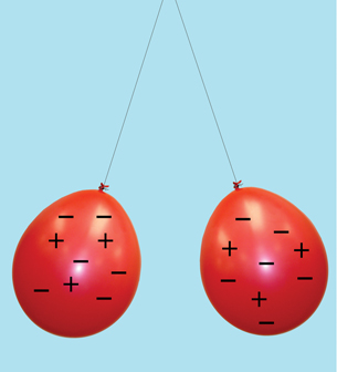
In this photo a balloon suspended by a thread is attracted to a wool sweater.

In this photo two balloons are suspended from a point on a ceiling. The balloons repel each other.
SC 5. Explain how the law of charges applies to the balloons shown in the preceding photographs.
SC 6. Recall your observations of the Van de Graaff generator lab earlier in this lesson. Provide one example of an object repelling and one example of an object attracting in the lab activity.
Self-Check Answer
SC 5. The law of charges states that like charges repel and unlike charges attract. The balloon and the sweater must have opposite charges since they are attracted to one another. The two balloons must have like charges since they repel one another.
SC 6. There are many examples of objects being repelled. The animal fur, the aluminum pie plates, and the confetti in the cup were all repelled by the Van de Graaff generator and each other. The first soap bubble was attracted to the Van de Graaff generator, while the other soap bubbles were repelled.
1.5. Page 3
Module 3—Electrical Phenomena
The Two Types of Charge

© smithcjb/iStockphoto
People developed an understanding of electricity gradually. Many of the earliest ideas came from everyday experiences. For example, if you scuff your feet while walking over a carpet, you can cause a charge to build up, which leads to a nasty shock when you touch a person or an object. Have you ever used these effects to give yourself or someone else a shock?
You’ll see from reading your textbook that observations from everyday experiences led to a series of experiments. These experiments established that there are, in fact, two types of electric charges.
The positive and negative signs added to these balloons are representations of the relative amount of charge on each balloon.
 Read
Read
Read the information found on the bottom half of page 512 and the top half of page 513 of your textbook. It outlines the contributions of Benjamin Franklin and others to the study of electricity.
 Self-Check
You can check your understanding by answering these questions:
SC 7. Identify the two types of electric charges.
SC 8. Refer to the “infoBIT” on page 513 of your textbook. Suggest a reason why doctors and nurses wear special slippers while working with patients receiving oxygen.
Self-Check Answers
SC 7. One type of electric charge is positive, while the other type is negative.
SC 8. Since oxygen is an essential reactant for combustion, even the tiniest sparks around patients who are receiving oxygen could create a significant fire hazard. The special slippers prevent the buildup of an electric charge, which could produce sparks that could start a fire.
Conductors and Insulators
© demarcomedia/shutterstock
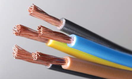
Today, electricity is essential to almost every daily activity. Whether it’s cooking, listening to music, or communicating with someone far away, electricity is likely involved. Cables, such as the ones shown in this photograph, are found in nearly every modern electrical device. The centre of the cable is made from copper while the outside is covered in a durable plastic coating. How does the arrangement of the electrons within a piece of copper make copper a good material for transferring electrical energy? How does the arrangement of the electrons within a piece of plastic make this material an ideal protective coating for the cable?
Read
To find out why electrical cables are built from these materials, read “The Modern Theory of Electrostatics” on pages 513 and 514 of your textbook.
Self-Check
You can check your understanding by answering these questions:
SC 9. Look around at your surroundings.
- Identify two materials that are conductors. Describe the essential characteristic that makes these materials conductors.
- Identify two materials that are insulators. Describe the essential characteristic that makes these materials insulators.
Self-Check Answers
SC 9.
- Answers will vary depending on your location. Typical examples of conductors might include a metal chair leg or the wires inside the cable of a pair of headphones. In all cases, conductors are metals in which the outermost or valence electrons are held loosely, enabling the material to conduct electricity.
- Answers will vary depending on your location. Typical examples of insulators might include a cushion on a chair or the soles of a pair of shoes. In all cases, insulators are non-metals in which the electrons are bound tightly to the nucleus, preventing the material from being a good conductor of electricity.
SC 10. The outermost electrons in copper atoms are free to move, which makes copper a good conductor. The copper core allows electricity to travel down the centre of the cable.
The outermost electrons in the atoms that form plastics are tightly bound to the nucleus and are not free to move, making plastic a good insulator. The plastic coating prevents the electricity travelling through the core of the cable from passing to unintended places through the walls of the cable.
1.6. Page 4
Module 3—Electrical Phenomena
Detecting Charge
In the Big Picture for this module, hikers could tell that lightning was about to strike if their skin started to tingle, their hair stood on end, or the pointed tips of metal equipment started to spark or glow. These all acted as detectors of the huge amounts of charge in a thundercloud overhead.
A more sophisticated way to detect the presence of a charged object is to use an electroscope. The most common type of electroscope consists of two thin, metal "leaves" suspended from a metal rod in a container. The conducting metal rod is supported by an insulating rubber stopper to ensure that charges do not pass from the rod to the container.
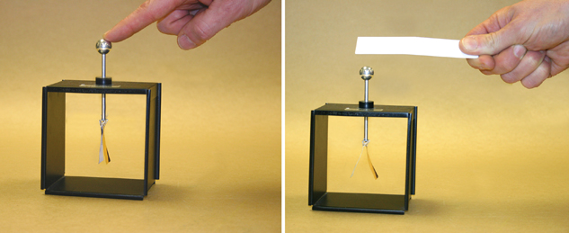
The photo on the left shows an electroscope that is being grounded by a finger. The leaves on this electroscope are together.
The photo on the right shows an electroscope that is brought near a negatively charged piece of plastic. The leaves on this electroscope repel one another and diverge.
grounding: the process of transferring charge to and from Earth; the symbol for ground is ![]()
Any excess charge on the electroscope can be removed by simply touching the knob with your finger. This is called grounding. Since the leaves are uncharged, they neither attract nor repel. Instead, the leaves hang loosely together.
If a negatively charged object is brought near the knob, the electrons on the knob are repelled, so they migrate to the leaves. Since both leaves are negatively charged, they repel one another and diverge. In the presence of a larger charge, the leaves separate even more.
 Self-Check
You can check your understanding by answering these questions.
SC 11. Compare the electrical conductivity of the metal rod, leaves, and knob with the electrical conductivity of the rubber stopper.
SC 12. Sketch a diagram to show why the leaves of an electroscope diverge in the presence of a negative charge. Remember that only the outermost electrons are free to move in a conductor; therefore, the positive charges remain locked in the nucleus of each atom.
SC 13. Sketch a diagram or provide a written description to show why the leaves of an electroscope diverge in the presence of a positive charge.
Self-Check Answer
SC 11. The rod, leaves, and knob of the electroscope are made of metal and, therefore, will conduct electricity. Electrons are able to migrate between the knob at the top and the leaves at the bottom since the metal is a conductor.
The stopper that supports the rod is made of rubber, which does not conduct electricity. Electrons would not be able to migrate from the rod to the metal case supporting the electroscope because the stopper is an insulator.
SC 12. The following diagram illustrates the mobility of the electrons by showing the positive charges evenly distributed while the outermost electrons of the atoms migrate to the leaves. Since the leaves are negatively charged, they repel one another and diverge.
SC 13. Again, only the outermost electrons are free to move in a conductor. The following diagram illustrates this point by showing the positive charges evenly distributed while the outermost electrons of the atoms migrate to the top. Since the leaves are left positive, they repel one another and diverge.
1.7. Page 5
Module 3—Electrical Phenomenon
Three Methods of Transferring Charge
Method 1: Charging by Friction

When you rubbed the balloon with the wool sweater earlier in this activity, you were charging both of these objects by friction. When two objects are charged this way, one always develops a positive charge while the other develops a negative charge. Why is this always the case? The answer has to do with the law of conservation of charge.
 Read
Read
You can learn about the law of conservation of charge and charging by friction by reading “Methods of Charging Objects” beginning on page 517 and ending on page 519 of your textbook.
 Self-Check
You can check your understanding by answering these questions:
SC 14. The balloon is made from a material that holds its electrons more tightly than wool.
- If a balloon is rubbed with wool, state the resulting charge on the balloon and on the wool.
- Explain why the process of rubbing the balloon with the wool does not generate additional electrons.
- Explain why it is essential for the balloon to be an insulator in order for the excess charges on its surface to remain in place.
Self-Check Answers
SC 14.
- The process of rubbing removes electrons from the wool and transfers them to the balloon. This leaves the wool positively charged and the balloon negatively charged.
- Rubbing the balloon with the wool did not generate additional electrons. The electrons were simply rearranged, since they were transferred from the wool to the balloon.
- Charging by friction involves transferring electrons from one object to another by rubbing. If the balloon were a conductor instead of an insulator, then the excess electrons would simply migrate across its surface and possibly return to the wool.
Three Methods of Transferring Charge
Method 2: Charging by Conduction
 Watch and Listen
You can see how an electroscope can be charged by conduction by selecting the “Charge by Conduction” button in the linked animation.
Read
The law of conservation of charge is also used to explain what occurs when an object is charged by conduction. To find out more about this, read “Charging Objects by Conduction” on page 519 of your textbook.
Self-Check
You can check your understanding by answering these questions:
SC 16. Use the idea of conduction to explain what happens when you get a shock from a doorknob after acquiring excess electrons from scuffing your feet across a floor.
SC 17. Explain what occurs when a positively charged object is touched to the knob of a neutral electroscope.
Self-Check Answers
SC 16. This is an example of conduction because electrons are transferred from your negatively charged fingertips to the neutrally charged doorknob as soon as you establish contact.
SC 17. When a positively charged object is touched to the knob of a neutral electroscope, some of the electrons within the electroscope are attracted to the positive object. After the electrons transfer from the electroscope to the positively charged object, the electroscope is left positively charged. Since each of the leaves is now positively charged, the leaves repel one another and diverge.
Three Methods of Transferring Charge
Method 3: Charging by Induction
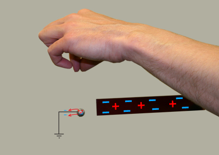
Watch and Listen
You can see how an electroscope can be charged by induction by selecting the “Charge by Induction” button in the linked animation.
Read
The most complex method of giving an object a charge is charging by induction. You can learn more about this procedure by reading “Charging Objects by Induction” on pages 520 and 521 of your textbook.
Self-Check
You can check your understanding by answering these questions:
SC 18. Define induction.
SC 19. The link Induction with a Negative Source shows a negative source charging an electroscope by induction. Write a concise description or illustrate with labels to explain what is occurring during each step of this process.
SC 20. Take one of your balloons and rub it vigorously with the wool sweater once again. Place the balloon high against a smooth, dry wall. See if the balloon will stick. If it does not, try recharging the balloon with the wool.
Concisely explain why the balloon can remain stuck to the wall and why this effect is able to last for many minutes.
SC 21. Sketch a series of diagrams to show how a positive source could charge an electroscope by induction. Write a concise description or illustrate with labels to explain what is occurring during each step of this process.
![]()
1.8. Page 6
Module 3—Electrical Phenomena
 Reflect and Connect
Retrieve the chart of your explanations of what happened using the Van de Graaff generator at the beginning of the lesson. Now that you have explored the three methods of transferring charge, you may need to reconsider your previous explanations.

Before you revise your chart, you need a little background information about the charge on the top of a Van de Graaff generator.
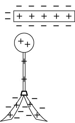
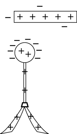
The globe of the Van de Graaff generator becomes negatively charged as excess electrons are transferred from a connection to the ground. This is done as a fast-moving belt rushes by metal combs at the top and bottom of the machine. Since the globe of the Van de Graaff generator is a conductor, the excess electrons redistribute themselves evenly over the surface of the globe. These excess electrons cannot return to the base because the rubber belt and the plastic column supporting the globe are insulators.
It takes work to force electrons to move from the ground connection at the base to the globe at the top. This is why input energy must be supplied by the motor of the generator to rotate the rubber belt on its two pulleys. You’ll learn more about the energy required to do work on moving charges in later lessons.
 Module 3: Lesson 1 Assignment
Remember to submit the answers to A 2 and A 3 to your teacher as part of your Module 3: Lesson 1 Assignment.
A 2. As you saw in the opening activity for this lesson, objects were placed on the globe of the Van de Graaff generator.
In each case, electrons were transferred from the negatively charged globe of the Van de Graaff generator to each of these objects. The result was that individual objects became negatively charged.
Use what you have learned in this lesson to explain the behaviour of each of these objects after the Van de Graaff generator was turned on. Submit your revised explanations for each of the following demonstrations to your teacher:
- animal fur
- aluminum pie plates
- confetti
 Try This: Explaining the Behaviour of the Soap Bubbles
Now that you have improved upon your explanations of the first three Van de Graaff generator demonstrations, reconsider the behaviour of the soap bubbles.
The behaviour of the soap bubbles is much more complex than that of the animal fur, the pie plates, or the confetti because the soap bubbles are subject to a sequence of interconnected events.
These events have been organized into the four steps listed below. In each step, describe what is happening and then explain. You can check your answers by clicking on the Description and Explanation buttons.
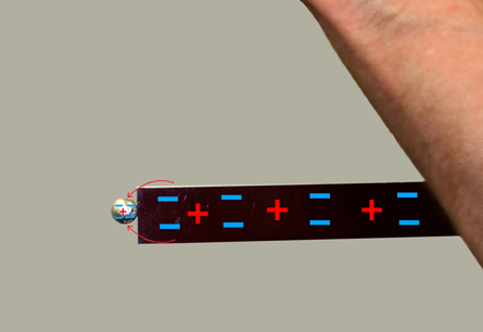
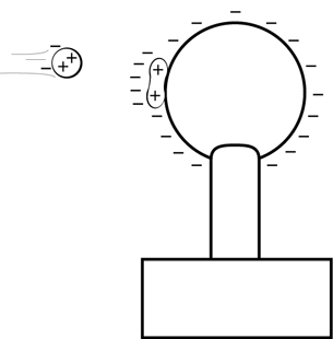
Step 1: Neutral soap bubbles are attracted to the negative globe.
For more information, click on Description and Explanation.
A stream of neutral soap bubbles is blown toward the negative globe of the Van de Graaff generator. As the bubbles get closer to the Van de Graaff generator, a charge shift occurs within the soap molecules. The side of the molecules closest to the negative globe becomes positively charged. The closest bubbles are attracted to the negative globe.
This is an example of induction because the electrons within the soap molecules shift due to the presence of the negative globe. Molecules of the soap solution are attracted to the Van de Graaff generator because the positive sides of these molecules are closer to the Van de Graaff generator than the negative sides.
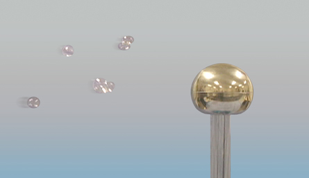
Step 2: The first soap bubble collides with the globe and becomes negatively charged.
For more information, click on Description and Explanation.
This step happens in an instant. Upon contact with the Van de Graaff generator, the soap bubble picks up excess electrons from the Van de Graaff generator. Then the negatively charged soap bubble bursts, sending tiny droplets of negatively charge soap into the air.
This is an example of charging by conduction because electrons are transferred to the molecules of the soap solution as they touch the negatively charged globe.
Step 3: The repelled tiny negative droplets collide with incoming soap bubbles.
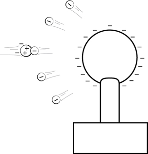
For more information, click on Description and Explanation.
The tiny droplets from the burst soap bubble are now repelled from the negatively charged Van de Graaff generator. A spray of negatively charged droplets fills the air around the globe. These negative droplets are attracted to the bubbles’ positive side (see step 1). Some of these droplets collide with incoming bubbles, adding excess electrons to the bubbles, making them negatively charged by conduction.
This is an example of charging by conduction because electrons are transferred to the incoming soap bubbles as they collide with the negatively charged droplets.
Step 4: Incoming bubbles are repelled and move away from the negatively charged globe.
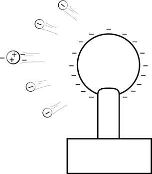
For more information, click on Description and Explanation.
The incoming soap bubble is now negatively charged, so the negatively charged globe repels it.
The incoming negatively charged soap bubble is now pushed away from the negatively charged globe because like charges repel.
 Big Picture Reflection
Connecting Bubbles and Lightning Strikes
In the previous section you worked at describing and explaining what happens to a soap bubble near the negatively charged globe of a Van de Graaff generator.
You might be surprised to know that the principles explained in this demonstration can also be applied to lightning.
 Read
Read
Carefully read the section called “How Lightning Gets Its Charge” on page 522 of your physics textbook. As you read this section, look for similarities between lightning and the soap bubble demonstration.
 Discuss
D 1. Summarize the piece from the textbook called “How Lightning Gets Its Charge” by writing or illustrating a series of steps that will concisely describe and explain what occurs in this process. Your result should be in a format similar to the steps used to describe and explain the soap bubble in the previous activity. Remember to add the answer to this question to your course folder.
D 2. Post your summary to the discussion area set up by your teacher. Compare your summary to at least one other explanation produced by another student. Identify similarities and differences between your work and the work of other students. Remember to add the answer to this question to your course folder.
D 3. If you were to update your explanation of lightning based on what you learned in D 2, what changes would you make? Remember to add the answer to this question to your course folder.
Module 3: Lesson 1 Assignment
Remember to submit the answer to D 4 to your teacher as part of your assignment.
D 4. Use your answers to Discuss questions D 1, D 2, and D 3 to revise your explanation of how lightning gets its charge. Submit your revised summary to your instructor as part of your assignment.
Discussion Scoring Guide
| Principles involved: Static electricity | ||||
Criteria |
Level 1 |
Level 2 |
Level 3 |
Level 4 |
Knowledge |
||||
Demonstrates understanding of the situation, physics principles and technology, and their connections. |
Demonstrates a vague and sometimes incorrect understanding of the physics principles involved. Obvious irrelevant or missing information. |
Demonstrates a basic understanding of the physics principles involved. May exhibit minor mistakes or vague information or application to the situation. |
Demonstrates a good understanding of the physics principles involved and applies them properly to the given situation. All necessary information is given. |
Demonstrates a superior understanding of the physics principles involved and their application to the situation. All applications are considered in detail. |
Reflection |
||||
The post shows reflection on one’s own and other students’ work. Contributes to the group discussion. |
Does not make an effort to participate. Seems indifferent to discussion. |
Occasionally makes meaningful reflections on the group’s efforts or discussions. Marginal effort is shown to become involved with the group or discussion. |
Frequently makes meaningful reflections on the group’s efforts and presents relevant viewpoints for consideration by the group. Interacts freely with group members. |
Regularly attempts to motivate the group discussion and delve deeper into concepts. Interacts freely and encourages all group members. |
Content and presentation of discussion summary |
||||
The information is logically arranged in a clear and concise manner. |
The information is poorly organized with many concepts implied. Irrelevant or rambling sentences make reading difficult. |
The information is somewhat organized with implied concepts. Excessive words or awkward sentences are used, which hinder reading. |
The information is well-organized and logically arranged. All concepts are explicitly explained. There are a few awkward but understandable sentences. |
The information is well- organized and very easy to understand. Well-worded sentences make reading pleasurable. |
Module 3: Lesson 1 Assignment
Remember to submit your Module 3: Lesson 1 Assignment, including question A 4 to your teacher for marks.
A 4. Do question 10 of “10.1 Check and Reflect” on page 523 of your physics textbook.
1.9. Page 7
Module 3—Electrical Phenomena
 Lesson Summary
At the start of this lesson you were asked two essential questions:
- Can the concepts that explain large-scale phenomena like lightning be explored using small-scale equipment like a Van de Graaff generator?
- How can these concepts explain what happens to charges within a cloud during a lightning strike?
You have seen that charged balloons, soap bubbles, and machines like a Van de Graaff generator can effectively model many of the key concepts that are essential to understanding electrostatics. These concepts include the attraction and repulsion of charges, the law of conservation of charge, and the three methods of transferring charge—by friction, by conduction, and by induction. All of these ideas come into play to describe how lightning gets its charge.
Lesson Glossary
grounding: the process of transferring charge to and from Earth
1.10. Lesson 2
Module 3—Electrical Phenomena
Lesson 2—Investigating Coulomb’s Law
 Get Focused

© NOAA US Gov
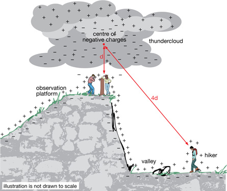
This is the young woman at the observation platform of a national park whom you met in the previous lesson. Recall that charges in a nearby thundercloud caused her hair to stand on end. Although the exact details of what happened that day are unknown, the following diagram shows what this scene may have looked like from a different perspective.

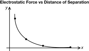
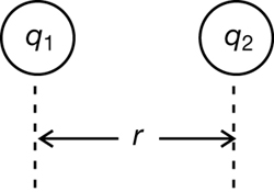
This illustration shows a hiker standing far below the platform, somewhere in the valley. Since the hiker is about four times as far from the negative charges in the cloud, the hiker is in a much safer location than the people on the platform. For the hiker in the valley, it would be unlikely that the charge in the cloud could induce a charge on strands of hair. There wouldn’t be a large enough force to make these hairs stand on end. If the distance were four times farther, how would the electrostatic force be affected? Would the force be ¼ as large for the hiker as for the people on the observation platform?
Charles de Coulomb, in 1785, investigated the precise relationship between electrostatic forces and distance of separation. Coulomb was a former military engineer. He used his engineering skills to design and build a precision device to explore the variables that affect electric forces. The results of his work provide a precise description of the electric force that exists between two charged objects separated by a known distance.
In this lesson you will focus on the following essential questions:
- What is Coulomb’s law, and how was this law determined using the results of experiments?
- Can Coulomb’s law predict the effect on electrostatic force if the distance of separation increases by a known amount? What does the answer to this question suggest about lightning safety?
 Module 3: Lesson 2 Assignment
Your teacher-marked Module 3: Lesson 2 Assignment requires you to submit a response to the following questions:
- Assignment—A 1 and A 2
You must decide what to do with the questions that are not marked by the teacher.
Remember that these questions provide you with the practice and feedback that you need to successfully complete this course. You should respond to all the questions and place those answers in your course folder.
1.11. Page 2
Module 3—Electrical Phenomena
 Explore

© Stephen Strathdee /shutterstock
A Link Between Electrostatics and Gravitation
Coulomb did not begin his work on determining the electric force law on his own. As the following timeline indicates, other scientists had already done much of the essential groundwork. You might be surprised to know that the essential ideas came from Isaac Newton’s work on gravitation.
Date |
Scientist |
Contribution to Coulomb’s Work |
|---|---|---|
1687 |
Isaac Newton |
Published his great book Mathematical Principles of Natural Philosophy, which included his three laws of motion and his law of universal gravitation:
|
1775 |
Benjamin Franklin |
Franklin noticed that a small cork inside a hollow, charged can experiences no force. The same cork experiences a force outside the can. He wrote to Joseph Priestly and asked him to repeat the experiment. |
1776-1777 |
Joseph Priestley |
Priestley verified Franklin’s results and realized a connection to Newton’s law of universal gravitation. Newton had explained in his book that an object would experience no force of gravity inside a hollow planet. He was able to show that this was the consequence of the “inverse squares law,” which says that gravitational force acting on two masses is inversely proportional to the square of the distance between their centres. Priestly instantly likened the cork to the object and the hollow can to the planet. Priestley suggested that this indicated that the force of electricity could also be an inverse square law. |
 Read
Read
To review the key features of Newton’s law of universal gravitation and to better understand what it means to say that this law is an “inverse square law,” read “10.2 Coulomb’s Law” on page 524 of your textbook. Pay special attention to the “Physics Insight” on the left-hand side of the page.
 Self-Check
You can check your understanding by answering these questions:
SC 1. List all the variables that influence the magnitude of the force of gravity.
SC 2. Describe how increasing the size of both masses influences the magnitude of the force of gravity.
SC 3. Describe how increasing the distance (r) between the two masses influences the magnitude of the force of gravity ![]()
SC 4. Mathematically express how increasing the size of both masses influences the magnitude of the force of gravity. In other words, write a proportionality statement.
SC 5. Mathematically express how increasing the distance (r) between the two masses influences the magnitude of the force of gravity. In other words, write a proportionality statement.
Self-Check Answers
SC 1. The magnitude of the force of gravity is affected by the mass of the two objects and the distance between their centres.
SC 2. As the masses increase, the force increases. This is a direct relationship.
SC 3. As the distance (r) between the two masses increases, the magnitude of the force of gravity ![]() decreases. This is an inverse square relationship.
decreases. This is an inverse square relationship.
SC 4. ![]()
SC 5. ![]()
Making Predictions about the Electrostatic Force
© Bill McKelvie/shutterstock
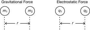
Given your answers to the previous questions, you should be able to speculate about the nature of the electrostatic force. The following graphic shows the possible connections between the gravitational force ![]() acting on two masses (m1 and m2) and the electrostatic force
acting on two masses (m1 and m2) and the electrostatic force ![]() acting on two charges (q1 and q2).
acting on two charges (q1 and q2).
 Try This
TR 1. Identify the variables that will likely influence the magnitude of the electrostatic force.
TR 2. Speculate on how increasing the size of charges q1 and q2 will influence the size of the electrostatic force.
TR 3. Speculate on how increasing the distance between the two charges would influence the magnitude of the electrostatic force.
1.12. Page 3
Module 3—Electrical Phenomena
Verifying Predictions about the Electrostatic Force
torsion balance: an instrument designed to measure small forces by the twisting of a thin wire
Although the thought processes used to answer the previous questions are very helpful as a starting point, it is important to verify these hypotheses with data collected from an experiment. Coulomb did this using a torsion balance. A detailed illustration of the torsion balance is shown in the following illustrations.

In Coulomb’s torsion balance, a horizontal, insulated rod is suspended by a thin, stiff fibre of silver wire. The wire twists when a force is exerted on sphere A, which is shown at the end of the rod. The force on sphere A causes the rod to rotate horizontally. The twisting of the wire can be measured at the suspension head at the top, which indicates the force acting on sphere A.
A simplified representation of this apparatus focuses on the suspension head at the top and the two charged spheres at the bottom. This simplified version shows how the variables of distance of separation (r) and charge (q) could be used to measure the electrostatic force
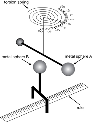
In this simplified scheme, the ruler can be used to measure the distance from the centre of sphere A to the centre of sphere B. If sphere A and sphere B were given like charges, a force would act on each sphere. This force would push the spheres apart. If sphere A were free to move, then it would be forced to rotate away from sphere B, causing the wire to twist. A larger force acting on sphere A would produce a greater twist in the wire, which could be indicated by the scale on the top.
Although Coulomb had no way of determining the exact amount of charge on an object, he did devise an ingenious method of varying the charge in a controlled way.
 Read
Read
To learn more about Coulomb’s method for varying charge, read page 528 in your textbook.
 Self-Check
You can check your understanding by answering this question:
SC 6. Coulomb used a third sphere, C, which was identical to sphere A and sphere B. Explain how Coulomb used sphere C to vary the charge on sphere B.
Self-Check Answer
SC 6. Sphere C was identical to sphere B, but it was neutral. If sphere C was touched by sphere B, then the charge on sphere B would be split evenly between spheres B and C. If sphere B began with an amount of charge that was ![]() , after being touched by sphere C, the charge on B would become half of the original value or
, after being touched by sphere C, the charge on B would become half of the original value or ![]() . This process could be repeated by first grounding sphere C before touching it to sphere B, which would remove half of the remaining charge on sphere B each time.
. This process could be repeated by first grounding sphere C before touching it to sphere B, which would remove half of the remaining charge on sphere B each time.
You will have an opportunity to collect data from a virtual torsion balance apparatus in the next investigation.
1.13. Page 4
Module 3—Electrical Phenomena
 Lesson 2 Lab: Simulating Coulomb’s Experiment
In this lab activity you will simulate what Coulomb did to derive the equation to describe the electrostatic force. This activity will be broken into two parts. The first part of this lab investigates the relationship between the distance of separation (r) on the electrostatic force ![]() , while the second part investigates the relationship between the amount of charge (q1 and q2) and the resulting electrostatic force
, while the second part investigates the relationship between the amount of charge (q1 and q2) and the resulting electrostatic force ![]() .
.
Part A: How the Electrostatic Force is Affected by Distance of Separation (r)
Purpose
In this part of the investigation you will examine how Coulomb gathered data from a torsion balance experiment to determine the relationship between the distance of separation and the electrostatic force. You will be given sample data to graph and analyze to find the relationship.
Materials
You will need a calculator, a pencil, an eraser, a straight edge or ruler, and a piece of graph paper. If you decide not to use graph paper, you will need a graphing calculator or a computer that has spreadsheet software to do graphing. Below is a diagram of Coulomb’s torsion balance apparatus set up for the experiment.

Variables
Before starting the experiment Coulomb had to identify the manipulated variable and predict what would happen when metal sphere A was released. Study the previous diagram, and answer the Self-Check questions about it.
 Self-Check
SC 7. Identify the type of force that causes the acceleration of sphere A.
SC 8. Determine if the force will push sphere A away from sphere B or toward sphere B. Support your answer.
SC 9. Assume that sphere B is fixed in position and that sphere A is free to rotate. Determine if the arm holding sphere A will rotate clockwise or counterclockwise (if viewed from above as shown in the illustration.)
Self-Check Answers
SC 7. The acceleration is caused by electrostatic force acting on sphere A. According to Newton’s third law, an equal force is acting in the opposite direction on sphere B.
SC 8. The force on sphere A will act to push it away from sphere B since each sphere has a negative charge and like charges repel.
SC 9. Sphere A will rotate counterclockwise since it is repelled from sphere B.
If the arm on the torsion balance rotates, it will cause the torsion spring to tighten with a certain force. This is indicated on the scale. Coulomb had predetermined the graduation of the force scale in grains of force. In this simplified version, the scale is set in units of force that will be referred to as F units.
Procedure
- Sphere B is initially given a negative charge by touching it to a charged rubber rod that was rubbed with fur. Since Coulomb did not have a precise value for the charge on sphere B, he simply referred to this charge as qB.
- Touch Sphere B momentarily to sphere A, which was initially neutral.
- With sphere A held stationary, place sphere B 1.0 cm away. Release sphere A, allowing the arm on the torsion balance to rotate. Measure the force acting on sphere A on the scale at the top of the torsion balance.
- Repeat the preceding step with sphere B set at the following distances from sphere A’s positions: 2.0 cm, 4.0 cm, and 8.0 cm.
- The results of all the trials are indicated in the diagrams shown in the Observations section. Note that the angles of rotation have been made large enough for you to make force measurements. In Coulomb’s actual apparatus, the angles of rotation were all less than 10°.
Self-Check
SC 10. Remember that spheres A and B are identical in size and both are made of metal.
- Describe what happens to the charge when sphere B is touched to sphere A.
- Determine and explain the total charge that is present on both spheres A and B after they touch.
- Determine and explain the charge that would be on each sphere after they were touched and separated.
Self-Check Answers
SC 10.
- Since sphere A and sphere B are conductors, electrons will flow from sphere B to sphere A until the charge on each is the same. This is an example of charging by contact.
- The total charge must be qB, in accordance with the law of conservation of charge.
- Since the original amount of charge qB is shared, the charge on sphere A will be
 and the charge on sphere B will be .
Observations
The following multimedia will show you the results when Coulomb released sphere A from different distances. Click on the “Next” button to see the different force and distance values and fill in the results for Self-Check 11.
Data
Self-Check
SC 11. Study the diagrams, and create a chart of data values showing the distance of separation and the corresponding force for each trial. Remember that you can use a graphing calculator or a spreadsheet instead of a paper chart.
Self-Check Answer
SC 11.
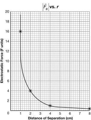
Distance (r) Between the Centres of the Two Charged Objects (cm) |
Electrostatic Force Acting on Sphere A (F units) |
1.0 |
16.0 |
2.0 |
4.0 |
4.0 |
1.0 |
8.0 |
0.3 |
Analysis
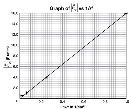
SC 12. Draw a graph of ![]() as a function of r. You can use the following steps as a guide:
as a function of r. You can use the following steps as a guide:
- Explain which variable is the manipulated variable, which variable is the responding variable, and which variables are held constant.
- Label the axis with the manipulated variable on the x-axis and the responding variable on the y-axis.
- Scale the axis and plot the points.
- Draw the line of best fit for this data.
Self-Check Answers
SC 12.
- In this experiment the distance is the manipulated variable since this variable is changed intentionally. The electrostatic force was the responding variable since the force acting on sphere A depended upon the distance value. The variables that were held constant in this experiment include the charge on each of the spheres.
- to d. There are two ways to graph the results. Method 1 uses pencil and graph paper. Method 2 uses a graphing calculator or computer. You are required to complete only one of the two methods.
Method 1: Using Pencil and Paper
You could also use your graphing calculator.
Method 2: Using a Graphing Calculator or a Computer
If you used a graphing calculator or computer software to answer this question, be sure to communicate your answer in the proper format.
Data Entry:
r (cm) entered into L1
F (F units) entered into L2
Window Settings:
x: [0,10, 1]
y: [0,20,1]
Plot Setup:
To plot F (F units) versus r (cm), enter L2 for y and L1 for x.
SC 13. Earlier in this lesson, the suggestion was made that the equation describing the electrostatic force that acts on one charge due to the presence of a second charge could be an inverse square relationship.
- Use adjacent pairs of data points to illustrate that
 varies as
  .
.
- Instead of sampling individual data points, a better way to demonstrate that Fe varies as is to manipulate the original data chart to produce a straight-line graph. Build a new data chart with columns for the distance (r), the new values that you will be plotting, and the electrostatic force, .
- Use the manipulated data from SC 13. b. to draw a straight line graph illustrating the inverse square relationship.
Self-Check Answers
SC 13.
- An inverse square relationship implies that if one variable increases by a factor of 2, then the other variable decreases by a factor of
 . This is due to the fact that the inverse square of 2 is
  or . This pattern is clearly shown between adjacent pairs of data points. For example, when the distance doubles from 1 cm to 2 cm, the value of the force is reduced from 16 F units to 4 F units, or by a factor of .
- and c. can be done two different ways. Method 1 uses pencil and paper. Method 2 uses a graphing calculator or computer. Both methods use curve straightening to change a curved graph into a straight line graph as you saw in Physics 20. You are required to complete only one of the two methods.
Method 1: Using Pencil and Paper
Distance (r) (cm) |
(F units) |
|
|---|---|---|
1.0 |
1.0 |
16.0 |
2.0 |
0.25 |
4.0 |
4.0 |
0.063 |
1.0 |
8.0 |
0.016 |
0.3 |
You could also use your graphing calculator.
Method 2: Using a Graphing Calculator or a Computer
Although the data chart will look the same, the use of technology allows a very efficient approach. Instead of completing four individual calculations to determine values for ![]() , simply define a third list in terms of the inverse square of all the values for r in L1.
, simply define a third list in terms of the inverse square of all the values for r in L1.
Data Entry:
r (cm) entered into L1
F (F units) entered into L2
![]() , determined by defining L3 as follows: “L3 = (1/L1)2”
, determined by defining L3 as follows: “L3 = (1/L1)2”
- You could calculate the answer using paper and pencil.
If you used a graphing calculator or computer software to answer this question, be sure to communicate your answer in the proper format.
Data Entry:
r (cm) entered into L1
F (F units) entered into L2
![]() entered into L3: “L3 = (1/L1)2”
entered into L3: “L3 = (1/L1)2”
Window Settings:
x: [0,1, 0.1]
y: [0,20,1]
Plot Setup:
To plot F (F units) versus ![]() , enter L2 for y and L3 for x.
, enter L2 for y and L3 for x.
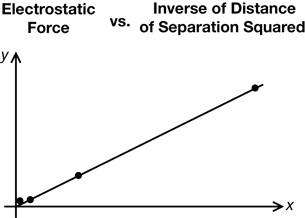
Part A Conclusion
Now that you have seen Coulomb’s observations and learned how to change the curved electrostatic force vs. distance of separation graph into a straight line graph you should have an understanding of how the two variables relate.
SC 14. Based upon your results for SC 13, write a mathematical expression describing the relationship between
Self-Check Answer
SC 14.
The electrostatic force ![]() is inversely proportional to the square of the distance (r2). Mathematically, this is written as
is inversely proportional to the square of the distance (r2). Mathematically, this is written as ![]() .
.
1.14. Page 5
Module 3—Electrical Phenomena
Part B: How Electrostatic Force is Affected by Charge Strength (q)
Purpose
In this part of the lab you will examine sample data from Coulomb’s torsion balance experiment to determine how varying the charge on one sphere can influence the electrostatic force on the other.
Materials
The only material needed is sample data from a torsion balance-type experiment. This data is provided for you in this investigation. To determine these values Coulomb used his torsion balance.
Background Information
In part A Coulomb used a negatively charged rod to give sphere A and sphere B the same charge. He used a third neutral sphere called sphere C, which was otherwise identical to spheres A and B, to vary the amount of the charge on sphere B.
Each time sphere C was touched to sphere B, the original charge on sphere B was split between spheres B and C. After sphere C was removed, sphere B was left with only half of the charge that it had before touching sphere C. Grounding sphere C each time and repeating this process provided a method for varying the charge on sphere B. Sphere A’s charge remained the same throughout the process.
Procedure
The first three steps of the procedure are the same as part A. Step four is where the two procedures differ:
- Give sphere B an initial negative charge by touching it to a charged rubber rod that was rubbed with fur. Since Coulomb did not have a precise value for the charge on sphere B, he simply referred to this charge as qB.
- Touch sphere B momentarily to sphere A, which was initially neutral.
- With sphere A held stationary, place sphere B 2.0 cm away. Release sphere A, allowing the arm on the torsion balance to rotate. Measure the force acting on sphere A on the scale at the top of the torsion balance.
- Ground sphere C, which is identical in size to sphere A and sphere B, to give it a charge of zero. Touch it to sphere B and then remove it.
- Return sphere A to a distance 2.0 cm away from sphere B and release it, allowing the arm on the torsion balance to rotate. Measure the force again.
- Repeat the preceding two steps to observe how the new charges on sphere B affect the electrostatic force.
Observations
The following table summarizes these results.
Data
Charge on Sphere A |
Charge on Sphere B |
Product of the Charges |
Electrostatic Force on Sphere A |
|---|---|---|---|
|
|
|
4 |
|
|
|
2 |
|
|
|
1 |
|
|
|
|
Analysis
 Self-Check
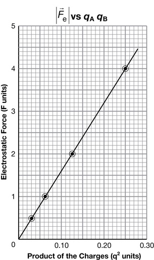
SC 15. Plot a graph of the electrostatic force ![]() versus the product of the two charges (qA qB).
versus the product of the two charges (qA qB).
Self-Check Answer
SC 15. You could calculate the answer using pencil and paper, or you could calculate the answer using your graphing calculator.
Method 1: Pencil and Paper Approach
Method 2: Using a Graphing Calculator or a Computer
Data Entry:
q1q2 (q2 units) entered into L1
F (F units) entered into L2
Window Settings:
x: [0,0.25, 0.01]
y: [0,4,0.1]
Plot Setup:
To plot F (F units) versus q1q2 (q2 units), enter L2 for y and L1 for x.
If you used a graphing calculator or computer software to answer this question, be sure to communicate your answer in the proper format.
Part B Conclusion
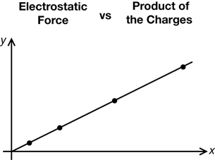
Now that you have seen the observations and analyzed them by graphing you should be able to describe the relationship.
SC 16.
- Describe the shape of the graph that you plotted.
- Use the shape of the graph to state the mathematical relationship between the electrostatic force and the product of the two charges.
Self-Check Answers
SC 16.
- The result of graphing electrostatic force
 versus the product of the charges (qA qB) can be a straight line.
- The electrostatic force is directly proportional to the product of the charges. Mathematically, this can be written as
 .
.
Lab Conclusion
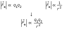
Now that you have completed Part A, you understand the relationship between the electrostatic force and the distance of separation. Since you have completed Part B, you also understand the relationship between the electrostatic force and the product of the charge. Now you need to combine your results to determine the equation that describes Coulomb’s law.
SC 17.Consider your conclusion for Part A and your conclusion for Part B. Based upon your results, state the mathematical relationship among the variables ![]() , qA, qB, and r.
, qA, qB, and r.
Self-Check Answers
SC 17. The electrostatic force ![]() is directly proportional to the product of the charges (qA qB) and inversely proportional to the square of the distance (r2).
is directly proportional to the product of the charges (qA qB) and inversely proportional to the square of the distance (r2).
Mathematically, this can be written as ![]()
1.15. Page 6
Module 3—Electrical Phenomena
 Reflect and Connect
The conclusions of Coulomb’s experimental work with the torsion balance enabled him to describe the factors that determined the magnitude of the electrostatic force.


© NOAA US Gov
Coulomb’s law: the magnitude of the electrostatic force between two charged objects is directly proportional to the product of the two charges on the objects and inversely proportional to the square of the distance of separation between their centres.
Coulomb’s law can provide insights into the circumstances described in the Get Focused section.
 Try This
TR 4. Recall your work from Lesson 1. Describe the process that caused the top surfaces of the objects under the thundercloud to develop a positive charge.
TR 5. The circumstances in this illustration are much more complex than the carefully controlled environment of Coulomb’s experiment. Identify at least two differences between the circumstances in the illustration and Coulomb’s work.
The answers to the previous question indicate that applying Coulomb’s law to the circumstances in the illustration will only yield a rough approximation of what may be occurring in terms of electrostatic forces.
Even with these limitations in mind, some valuable insights can be gained into lightning safety.
 Self-Check
SC 18. The illustration shows that the hiker is four times farther from the negative charges in the thundercloud than the people on the observation platform.
- Use Coulomb’s law to provide a rough comparison of the electrostatic force that would act on a similarly charged strand of hair in each location.
- Do you think it is reasonable to assume that a strand of hair would have a similar charge in each location? Explain concisely.
- How does your answer to SC 18.b. affect your estimates of forces in SC 18.a.?
Self-Check Answers
SC 18.
- Assuming that the strands of hair in both locations are similarly charged means that distance would be the only difference. Since the distance is four times farther for the hiker, the resulting electrostatic force acting on a strand of hair would be only
 th as much for the hiker. This is because the inverse square of a fourfold increase is (
 )2 or .
- No, it is not reasonable to assume that the strands of hair would have similar charges in each location. The induced charge on a strand of hair for the hiker would be less due to the larger distance of separation between the hair strand and the cloud.
- If a strand of hair on the head of the hiker had a smaller induced charge, then the resulting electrostatic force exerted by the charges in the cloud would be even less than the estimate from SC 18.a.
 Big Picture Reflection
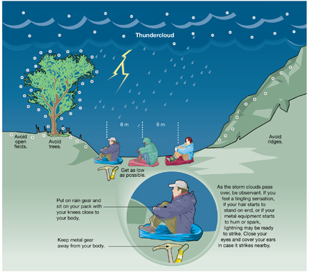
Imagine you are out hiking and are surprised by a sudden thunderstorm. Based on Coulomb’s law, what are the strategies for protecting yourself?
The strategies are:
- Avoid high spots, or very open areas; look for low areas.
- Sit down in a tucked position to get further from the clouds and prevent charge build up on extremities (arms, head and legs).
- Wear and/or sit on some insulating plastic, if possible.
- Get rid of metal objects that could conduct electric charges.
- Close your eyes and cover your ears to protect yourself from any nearby lightning strikes.
Does Coulomb’s law validate the recommendations shown in this illustration?
Store your thoughts in your Physics 30 course folder.
 Module 3: Lesson 2 Assignment
Remember to submit your Module 3: Lesson 2 Assignment to your teacher for marks. If you are not familiar with curve straightening refer back to Self Check 13 for an example.
A 1. Answer questions 25. a., b., c., and d. on page 541 of your textbook.
A 2. A student is investigating Coulomb’s law. The student measures a force of +2.00 × 10⁻³ N between the two charged spheres.
- Explain how you can tell whether the charges are both positive, both negative, or positive and negative.
- Describe two methods that the student could use to increase the force to 64 times its current value.
- The student touches one of the spheres with an equally sized neutral sphere and then removes the neutral sphere. The student then moves one of the spheres so the distance is three times the original distance. What is the ratio of the original force to the new force?
1.16. Page 7
Module 3—Electrical Phenomena
 Lesson Summary
At the start of this lesson you were asked two essential questions:
- What is Coulomb’s Law, and how was this law determined using the results of experiments?
- Can Coulomb’s law predict the effect on electrostatic force if the distance of separation increases by a known amount? What does the answer to this question suggest about lightning safety?
You examined sample data from a Coulomb-type experiment, and you analyzed this data using the techniques of graphical analysis. This work illustrated the essential characteristics of Coulomb’s law:
![]()
This law means that if the charges are held constant and the distance of separation increases by some factor, then the effect on the resulting electrostatic force can be predicted. For example, if the distance increases by a factor of four, then the electrostatic force would be ![]() th its original value. In terms of lightning safety, a wise strategy is to seek low ground—maximize the distance of separation between you and the cloud.
th its original value. In terms of lightning safety, a wise strategy is to seek low ground—maximize the distance of separation between you and the cloud.
In the next lesson you will continue your work with Coulomb’s law as you consider how much charge is actually transferred in a lightning strike.
Lesson Glossary
Coulomb’s law: the magnitude of the electrostatic force between two charged objects is directly proportional to the product of the two charges on the objects and inversely proportional to the square of the distance of separation between their centres
torsion balance: an instrument designed to measure small forces by the twisting of a thin wire
1.17. Lesson 3
Module 3—Electrical Phenomena
Lesson 3—Applying Coulomb’s Law
 Get Focused
Ernie Blair, Huntsville-Madison Co. (AL) 9-1-1 Center
This photograph was taken the day after a thunderstorm. Lightning struck the pole and then followed the guy wire down into the sandy soil. Closer inspection reveals one of the effects of the lightning—some of the sand was turned into glass.
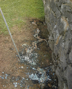
Ernie Blair, Huntsville-Madison Co. (AL) 9-1-1 Center
When lightning strikes the sandy soil, the extremely high temperature causes the silica in the sand to melt. The rapid cooling of this molten material forms glass. The next photograph shows a close-up of white silica glass formed by a lightning strike. Note the grains of sand melded to the outside surface of the glass.
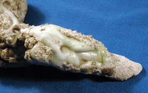
Photo by Stan Celestian, Glendale Community College Arizona.
Although the white glass has a smooth appearance, on the atomic scale, the silica in the glass has formed crystals with the main building block being a pyramid shape. In the following ball-and-stick model, the white ball in the centre represents a silicon atom; the four red balls surrounding it represent oxygen atoms. The oxygen atoms are actually much larger than the silicon atom, but they have been reduced in size to make the detail of the inner structure more visible.
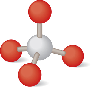
Each bond forms because of an unequal sharing of electrons. Each oxygen atom has a slightly negative charge, and the central silicon atom has a slightly positive charge. The result is a tetrahedral shape that is perfectly symmetrical: the values for the angles and the distances of separation are the same for each oxygen-silicon bond. Why does nature produce this kind of symmetry? The answer has to do with Coulomb’s law.
In this lesson you will apply Coulomb’s law to the exploration of both large-scale and extremely small-scale phenomena:
- How much charge is transferred in a lightning strike, and how is this amount of charge measured?
- How can Coulomb’s law be applied to predict the net force acting on one point charge due to the presence of other point charges? How does this sort of analysis relate to the symmetry found in crystals?
 Module 3: Lesson 3 Assignments
Your teacher-marked Module 3: Lesson 3 Assignment requires you to submit a response to the following questions:
- Assignment—A 1, A 2, A 3, and A 4
You must decide what to do with the questions that are not marked by the teacher.
Remember that these questions provide you with the practice and feedback that you need to successfully complete this course. You should respond to all the questions and place those answers in your course folder.
1.18. Page 2
Module 3—Electrical Phenomena
 Explore
An Equation for Coulomb’s Law

© Adrian Matthiassen/shutterstock
How would you describe the amount of charge delivered in a lightning strike or calculate the forces that act on the tiny charged particles within a crystal? You need values that can be described with units of measure and an equation for the electrostatic force. In the last lesson you learned that Coulomb’s work enabled him to describe the factors that affected the magnitude of the electrostatic force.
![]()
Although this mathematical expression describes Coulomb’s law, it is not an equation. The left-hand side does not equal the right because a proportionality constant (k) is missing. The proportionality constant enables the left side to be equal to the right by taking into account the units for charge, distance, and force.
 Read
Read
You can learn how units were considered in building the equation for Coulomb’s law by reading from the top of page 529 to the middle of page 530 in your textbook.
 Self-Check
You can check your understanding by answering these questions.
SC 1. Complete the following graphic to summarize the quantities in the equation for Coulomb’s law as well as the units for each of these quantities.
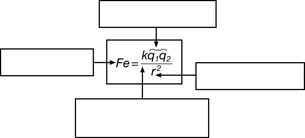
Quantity |
Units |
electrostatic force |
Newtons (N) |
Coulomb’s constant |
|
charge |
|
distance |
SC 2. Provide two examples that illustrate the size of a coulomb as a unit for charge.
Self-Check Answers
SC 1.
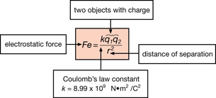
Quantity |
Units |
electrostatic force |
Newtons (N) |
Coulomb’s constant |
|
charge |
coulombs (C) |
distance |
metres (m) |
SC 2. The coulomb is a huge unit of charge. It is the amount of charge that could be transferred in a lightning strike. Alternatively, a coulomb corresponds to the amount of charge on 6.25 × 10¹⁸ electrons.
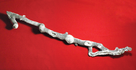
Photo by Stan Celestian, Glendale Community College Arizona.
 Try This
TR 1. Starting with Coloumb’s law derive the units for Coulomb’s constant ![]() .
.
As you saw in Get Focused, this piece of glass was formed as lightning penetrated sand. The presence of air and moisture in the silica resulted in an explosive expansion of the silica as many coulombs of charge surged into the ground. Note the swollen lumps formed by the rapid expansion of super hot bubbles. This sample is, in fact, hollow—a fragile glass tube.
The precise arrangement of the silicon and oxygen atoms within the glass crystals is a consequence of Coulomb’s law. However, the analysis is quite complex, requiring you to consider the vector nature of forces.
To prepare for this, the next part of this lesson will lead you through a series of examples that will gradually increase in complexity. By the time you have completed the last example, you should be ready to revisit the arrangement of the atoms in the crystal of glass.
1.19. Page 3
Module 3—Electrical Phenomena
Calculations with Coulomb’s Law
Dealing with Signs of Charges

© digitalife/shutterstock
![]()
The force of gravity is always an attracting force, acting to pull one mass toward another. In the previous photo, Earth is attracted to the sun.

![]()
The electrostatic force can be an attracting force or a repelling force, depending upon the sign of the charges. In the previous photo, balloon 1 repels balloon 2, since each balloon has a negative charge.
It is truly remarkable that two of the most fundamental laws in physics, which describe completely different phenomena and are based on completely different observations, should be so similar. The reasons for these similarities remain a mystery. However, it would be misleading to say that these forces are identical because there are some important differences.
When you solve problems with Coulomb’s law, it is important to substitute only the magnitude of the charges into the equation. The signs of the charges are considered after the calculation is complete to determine the direction of the resulting force.
 Read
Read
Do “Example 10.1” on page 530 in your textbook.
 Self-Check
Use this question to confirm your understanding of example 10.1.
SC 3. Complete the “Practice Problem” on page 530 of your textbook.
Self-Check Answers
SC 3.
Given
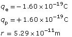
Required
![]()
Analysis and Solution
![]()
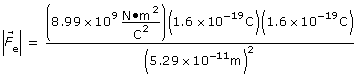
Note that the signs of the charges were not substituted into the equation.
![]()
![]() [attraction], since opposite charges attract
[attraction], since opposite charges attract
Paraphrase
The electrostatic force of 8.22 × 10⁻⁸ N pulls the electron toward the proton. This same force pulls the proton toward the electron.
Calculations with Coulomb’s Law
Using the Law of Conservation of Charge
Sometimes the law of conservation of charge plays a role in Coulomb’s law calculations. The two objects with different charges are first touched together and then separated before an electrostatic force is calculated.
Read
Do “Example 10.2” on page 531 of your textbook.
Self-Check
Use this question to confirm your understanding of example 10.2.
SC 4. Complete the “Practice Problem” on page 531 of your textbook.
Self-Check Answers
SC 4.
Given
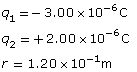
Required
![]()
Analysis and Solution
Step 1: Determine the charge on each sphere after they touch.
Apply the law of conservation of charge to the system of the two spheres:
total charge after touching = total charge before touching
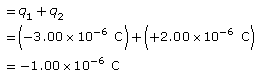
Since the total charge after the spheres touch is divided equally between the two identical spheres
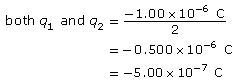
Step 2: Determine the electrostatic force acting on each sphere.
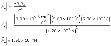
![]() [repulsion], since like charges repel
[repulsion], since like charges repel
Paraphrase
The electrostatic force of 1.56 × 10⁻¹ N acts on sphere 1 and pushes it away from sphere 2. The same force acts on sphere 2, pushing it away from sphere 1.
 Module 3: Lesson 3 Assignment
Remember to submit your answer to A 1 as part of your Module 3: Lesson 3 Assignment to your teacher for marks.
A 1. Answer question 12 on page 540 of your textbook.
1.20. Page 4
Module 3—Electrical Phenomena
Calculations with Coulomb’s Law
Three Charges Forming a Line
If there are three charges arranged along a straight line, then the calculation of the net electrostatic force on any one of the three charges requires you to take into consideration the vector nature of forces.
 Read
Read
Read the first two paragraphs on page 532 of your physics textbook, and then read “Example 10.3.” Be sure to follow the solution carefully.
 Self-Check
Use these questions to confirm your understanding of “Example 10.3.”
SC 5. Complete “Practice Problems” 1 and 2 on page 532 of your textbook.
Self-Check Answers
SC 5.
- The fact that sphere A and sphere C have the same charge means that the distance of separation is the only factor that will produce a difference in the electrostatic forces. In this case, the fact that the force varies inversely with the distance squared provides the key to drawing the free-body diagram. Since sphere C is two times farther away than sphere A, the electrostatic force exerted by sphere C must be (
 )2 or
)2 or  as large as the electrostatic force exerted by sphere A.
This explains why is four times longer than
  .
.
- The net electrostatic force on sphere B is represented by a vector three units long directed to the left. This is the result of the vector addition of , which is one unit long and directed to the right, combined with which is four units long and directed to the left.
In the previous example and the practice problems, the fact that two of the charges had the same magnitude allowed symmetry to simplify the solution. The next problems are slightly more complex because this symmetry is not present.
Read
Do “Example 10.4” on page 533 of your textbook. Be sure to follow the solution carefully.
Self-Check
Use this question to confirm your understanding of “Example 10.4.”
SC 6. Complete “Practice Problem” 1 on page 533 of your textbook.
![]()
 Module 3: Lesson 3 Assignment
Remember to submit your answers to A 2 and A 3 as part of your Module 3: Lesson 3 Assignment to your teacher for marks.
A 2. Do “Applications” problem 8 on page 538 of your textbook.
A 3. Do “Knowledge” problem 13 on page 540 of your textbook.
 Did You Know?
Some samples of the glass formed by lightning strikes can be thousands or even millions of years old. When the glass was formed, miniscule bubbles of trapped gases were sealed within the delicate glass linings. In a sense, these structures can be thought of as a collection of miniature sealed test tubes, storing pockets of gas that reflect the condition of soil and atmosphere very long ago. Scientists studying long-term patterns of climate change are beginning to utilize “lightning glass” as a potential source of data.
Photos provided by Stan Celestian, Glendale Community College Arizona.
Calculations with Coulomb’s Law
Three Charges Forming a Triangle
The glass crystal from the Get Focused section did not have the charges arranged in a straight line; instead, they were arranged in triangular shapes.
When three charges form a triangle, a calculation of the electrostatic force requires a two-dimensional vector treatment. This means that directions need to be expressed using either the polar method or the navigator method.
Read
Do “Example 10.5” on page 534 of your textbook. Be sure to follow the solution carefully.
Self-Check
Use this question to confirm your understanding of “Example 10.5.”
SC 7. Complete “Practice Problem” 2 on page 534 of your textbook.
Self-Check Answers
SC 7.
Given
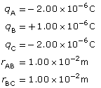
Required
to find the net force acting on sphere B, ![]()
Analysis and Solution
Step 1: Determine the direction of the forces.
The charge on sphere A is negative, and the charge on sphere B is positive. Therefore, the electrostatic force of qA on qB is an attractive force, pulling qB to the left. Similar thinking explains why the electrostatic force of qC on qB is an attractive force, pulling qB towards the bottom of the page.
If the polar method is used, then the following free-body diagram illustrates the forces acting on q2.
Note that since the spheres A and C have equal charges, and since these two spheres are the same distance from sphere B, ![]() is the same length as
is the same length as ![]() . This symmetry can be used to simplify the solution.
. This symmetry can be used to simplify the solution.
Step 2: Calculate the magnitude of the forces acting on sphere B.
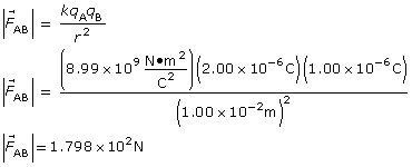
It is not necessary to do a separate calculation for the magnitude of ![]() since the calculation will be identical to that for
since the calculation will be identical to that for ![]() . Therefore,
. Therefore,
![]()
Step 3: Calculate the net electrostatic force on sphere B.
![]()
At this point, it is critical to realize that this equation is describing a two-dimensional vector addition. This means that the net force will be the resultant formed by adding ![]() and
and ![]() head to tail.
head to tail.
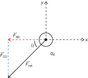
Since the net force is the hypotenuse of a right-angled triangle, the Pythagorean theorem can be used to find the magnitude of ![]() .
.
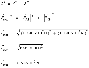
The fact that ![]() and
and ![]() have the same length means that the acute angle for
have the same length means that the acute angle for ![]() must be 45°. Using the polar method, the direction of
must be 45°. Using the polar method, the direction of ![]() can be determined by measuring counterclockwise from the x-axis.
can be determined by measuring counterclockwise from the x-axis.
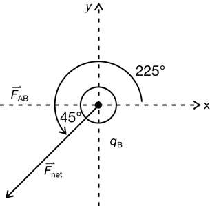
The direction of the net force is 225° using the polar method. If the navigator method were used, then south would replace the negative y direction and west would replace the negative x direction. The direction of the net force would be 45° south of west.
Paraphrase
The net electrostatic force acting on sphere B is 2.54 × 10² N [225°].
The previous example and practice problem show how powerful a systematic approach to problem solving can be. Did you recognize that this method of dealing with vectors using the polar or the navigator methods stemmed directly from your work with momentum earlier in the course? Even though the topic is no longer momentum, the same techniques work. This isn’t good luck—it is by design. Remember, the whole idea is to use the same overall strategies throughout the course so that you can become a successful problem solver.
As long as you take your time and consistently follow the recommended approach, even the most complicated problems can be solved. The key is to make effective use of diagrams—both vector diagrams and free-body diagrams.
Keep this in mind as you attempt the most complicated type of Coulomb’s law problem.
Open the multimedia learning object called Coulomb’s Law in 2D.
Read
Read “Example 10.6” on pages 535 to 537 of your textbook. Read the solution carefully. As you read, try to anticipate the next step in the solution.
Module 3: Lesson 3 Assignment
Remember to submit the answer to A 4 as part of your Module 3: Lesson 3 Assignment to your teacher for marks.
A 4. Do “Applications” question 24 on page 540 of your textbook.
1.21. Page 5
Module 3—Electrical Phenomena
 Reflect and Connect

In the Get Focused section you were asked to consider the symmetry of a crystal within silica glass. In the ball-and-stick model that was presented, a red ball represented each oxygen atom. These atoms have a slight negative charge. The central white ball represents a silicon atom that has a slight positive charge.
 Try This
TR 2. Consider the electrostatic force exerted by the top-most oxygen atom on the central silicon atom. Identify the direction of this force.
TR 3. Consider the net electrostatic force exerted by the three oxygen atoms on the bottom of the central silicon atom. Use your knowledge of vectors to explain how it could be possible for the direction of this net force to be straight down, in the opposite direction of the force exerted by the oxygen atom on the top.
TR 4. Given your answers to the previous two questions, explain how, because of the four oxygen atoms, it could be possible for the net force acting on the silicon atom to be zero.
TR 5. Suppose someone attempted to apply Coulomb’s law to calculate the net force on the silicon atom due to all four oxygen atoms in this crystal. Would it be sufficient to work only with x and y components of the individual forces? Suggest a more successful approach.
TR 6. Each of the oxygen atoms in this crystal has a slight negative charge. Therefore, each oxygen atom experiences a net repelling force due to the presence of the other three oxygen atoms. Identify a force that could counter this net repelling force.
 Big Picture Reflection

© james steidl/iStockphoto
Take a few moments and think about your answers to the questions in the Reflect and Connect section. The fact that the oxygen atoms are negatively charged and the central silicon atom is positively charged means that electrostatic forces apply to this situation. However, the net electrostatic force on each atom is zero. In other words, the forces are in a state of equilibrium. The angles and distances between the atoms simply describe the overall state of this system when the forces are balanced.
Given the central role played by the electrostatic force, it is not a stretch to say that the shape of this crystal is a direct consequence of Coulomb’s law. The same thinking could apply to almost any crystal. Keep this in mind the next time you look at a snowflake.
 Going Beyond

© Jhaz Photography/shutterstock
Other Effects of Lightning on the Environment
In this lesson you learned about some of the effects of lightning striking the ground. The silica in sand can be turned into glass because the temperature inside a single lightning bolt can exceed 30 000°C—that’s five times hotter than the surface of the sun!

© 2008 Jupiterimages Corporation
These high temperatures explain why lightning strikes are often a source of wildfires. In both the boreal forest ecosystem and the prairie grassland ecosystem, a fire started by lightning can have a rejuvenating effect since fires started by lightning strikes burn away dead and overcrowded trees, clearing the way for new growth; the combustion reaction also releases nutrients into the soil to nourish the next generation of the forest, leading to a healthy diversity in both the plant and animal communities.
Using Lightning as a Technology

© Mark R/shutterstock
First Nations people have lived in Alberta for thousands of years. They knew about the connections between the fires produced by lightning strikes and their beneficial long-term effects on the ecosystem. Where lightning caused a fire, there would be exceptionally lush vegetation in following years, which would attract animals such as bison, drawn to feed on the vegetation. Clearly, lightning was a natural phenomenon that was to be respected for both its destructive and beneficial effects.
 Self-Check
SC 8. The traditional ecological knowledge of the First Nations people developed through living in the environment for hundreds of generations. Part of this knowledge was informed by the natural cycle of forest rejuvenation of which fire is a part. Suggest a reason why this knowledge would be crucial to the survival of indigenous people in this environment.
Self-Check Answers
SC 8. First Nations people depended upon the resources found in the local environment to meet their basic needs: food, clothing, and shelter. It was critical to be able to predict where the best locations would be for the growth of plant material that would attract game. Knowing that an area struck by lightning could be bountiful in following years could improve the ability of people to survive in that area.
 Module 3: Lesson 3 Assignment
Remember to submit your Module 3: Lesson 3 Assignment to your teacher for marks.
1.22. Page 6
Module 3—Electrical Phenomena
 Lesson Summary
At the start of this lesson you were asked some essential questions:
-
How much charge is transferred in a lightning strike, and how is this amount of charge measured?
-
How can Coulomb’s law be applied to predict the net force acting on one point charge due to the presence of other point charges? How does this sort of analysis relate to the symmetry found in crystals?
In this lesson you’ve learned more about the enormous amounts of charge that a lightning strike can deliver between cloud and Earth. Although a strike of 1 C is typical, it is not unheard of for a single strike to deliver more than 30 C of charge. The high temperatures associated with this phenomenon can turn ordinary sand into crystals of silica glass and initiate wildfires.
Coulomb’s law can be used to calculate the net force on one point charge due to other point charges. The solutions to these sorts of problems require you to consider the vector nature of the electrostatic forces. The shapes of crystals are a consequence of charged particles aligning themselves so that the electrostatic forces are balanced.
In the next lesson you will use Coulomb’s law to explain electric fields and electrical phenomena.
1.23. Lesson 4
Module 3—Electrical Phenomena
Lesson 4—Electric Fields
 Get Focused
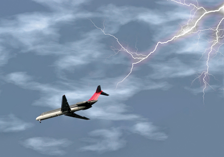
© Rose Hayes/shutterstock
Have you ever been on an airplane as it flew through a lightning storm? You may have seen an eerie blue glow on the wing tips. This unusual effect is an electrostatic phenomenon called St. Elmo’s fire.
St. Elmo’s fire was thought to indicate good luck to sailors in ancient times, because the tall masts of the ships would sometimes glow with a blue light following a bad storm. They believed it was a sign of salvation from the patron saint of sailors, St Ermo—the mispronunciation of the saint’s name was given to the fiery glow.
Although it is generally harmless, St.Elmo’s fire may have played a role in an airplane crash in 1959; an airplane flew into a stormy Italian sky and crashed just 12 minutes later.
The investigators who examined the crash site concluded that the accident was likely caused by an electrical discharge from St. Elmo’s fire, which they suspected had ignited vapors from the aviation fuel. The accident prompted Lockheed, the aircraft’s manufacturer, to install a flame-arrester screen on the vent pipe openings of its aircraft to eliminate the potential for St. Elmo’s fire to become a bad omen in stormy skies.
Though such accidents can now be prevented, St. Elmo’s fire still shows up on airplane wing tips and propellers. The explanations of this phenomenon involve the effects of strong electric fields.
In this lesson you will answer the following essential questions:
- What is an electric field, and how can it be described and analyzed?
- What exactly is St. Elmo’s fire, and why does it occur at the end of pointed surfaces?
 Module 3: Lesson 4 Assignments
Your teacher-marked Module 3: Lesson 4 Assignment requires you to submit a response to the following:
- Assignment—A 1, A 2, A 3, and A 4
- Discuss—D 4
You must decide what to do with the questions that are not marked by the teacher.
Remember that these questions provide you with the practice and feedback that you need to successfully complete this course. You should respond to all the questions and place those answers in your course folder.
1.24. Page 2
Module 3—Electrical Phenomena
 Explore
Action at a Distance
Throughout this course, you have had many opportunities to observe electrostatic forces acting on charged objects. In many cases, the force was able to produce an observable effect even though the objects were not touching.
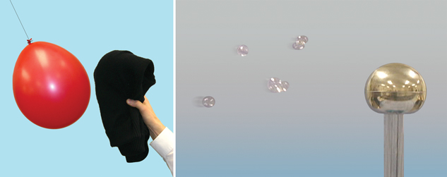
How were the positive charges on the sweater able to exert an electrostatic force on the negative charges on the balloon, even though the sweater was not touching the balloon? How was the negatively charged globe of the Van de Graaff generator able to exert forces on the soap bubbles, even though the Van de Graaff generator was not touching the bubbles?
field: a region of influence surrounding an object through which a force operates
These questions illustrate an important property of the electrostatic force: the force can act on a distant object without any apparent contact. This property has been called “action at a distance.” But naming this property is not the same as explaining it. After all, how does “action at a distance” work? What mechanism enables the electrostatic force to act through space? The answer to these riddles relates to an idea that you studied in previous courses—the concept of a field.
 Read
Read
You can learn more about how the concept of a field explains “action at a distance” by reading pages 542, 544, 545, and the bottom of page 546 of your textbook.
 Self-Check
SC 1. Electrostatics is not the only branch of physics that utilizes the concept of a field.
- Identify another type of force that uses the field concept to explain “action at a distance.”
- Support your answer to the previous question by briefly describing an example of how the concept of a field is used to explain action at a distance for the force you identified.
Self-Check Answers
SC 1.
- The field concept is used to explain how the force of gravity is able to act across empty space to keep distant objects in orbit.
- This is one possible approach. As a space module approaches the moon, the path of the space module changes due to the influence of the moon’s gravitational force of attraction. Even though the moon is not touching the space capsule, the moon’s gravitational field acts upon the space capsule. The moon’s gravitational field is a property of the space around the moon that enables it to exert a gravitational force on the space capsule.

NASA
Reviewing Gravitational Fields
Before you begin your study of electric fields, you may find it helpful to review what you have learned about gravitational fields from previous courses. A satellite in orbit around Earth is a good example of gravitational fields at work.
The Hubble Space Telescope moves at about 8 km/s as it orbits about 600 km above Earth’s surface. It’s natural to wonder why an object moving so quickly, so far from the planet, stays in orbit. Shouldn’t this satellite just fly off into space?
Read
To answer this question, think about Earth’s gravitational field. If you need help remembering how Earth’s gravitational field acts on objects in orbit, read pages 200 and 201 of your textbook.
Self-Check
SC 2. Earth’s gravitational field can be described by a field diagram and by an equation.
- Describe the direction of Earth’s gravitational field.
- Although Earth’s gravitational field is invisible, it can be represented with a diagram showing gravitational field lines. Sketch a diagram representing Earth’s gravitational field. Use this diagram to compare the strength of Earth’s gravitational field at locations close to the planet and far from the planet.
- Compare the direction of the gravitational force of Earth acting on the Hubble Space Telescope to the direction of Earth’s gravitational field at the same location.
- Define gravitational field strength.
- State the equation for gravitational field. How does this equation support your answer to part c?
- Explain the difference between gravitational force and gravitational field.
Self-Check Answers
SC 2.
- Earth’s gravitational field is directed toward the centre of the planet.
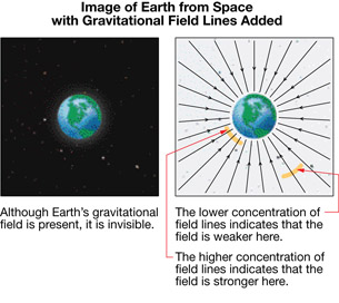
- The gravitational force of Earth exerted on the Hubble Space Telescope is directed toward the centre of the planet. The gravitational field of Earth points in the same direction at this location.
- Gravitational field strength is defined as the gravitational force per unit mass at a specific location.
- The equation is

This equation is a vector equation, with the gravitational field and the gravitational force pointing in the same direction.
- Gravitational force is the attractive force between any two objects due to their masses. The magnitude of the gravitational force can be experienced as a pull that can be measured with a spring scale calibrated in newtons.
Gravitational field is the invisible region of influence that surrounds a source mass. The strength of the gravitational field is the ratio of the gravitational force per unit of test mass. The strength of the gravitational field can only be observed indirectly by observing the behavior of test bodies.
Equations for Gravitational Field
A vector equation emphasizes that the gravitational field and the gravitational force act in the same direction.
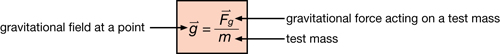
This equation provides a way to calculate the strength of the gravitational field in newtons per kilogram. Gravitational field strength can also be calculated in another way. Substituting Newton’s law of universal gravitation into the previous equation leads to an alternative equation that describes gravitational field strength.

Both equations for calculating the magnitude of the gravitational field for a point in space contain a mass variable, but these masses refer to different things.
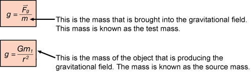
 Did You Know?
In Physics 20 you normally used m/s2 as the units for gravitational fields, which works very well for kinematics. In Physics 30 you will see N/kg, which is similar to the units for electric field strength of N/C.
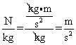
Self-Check
How well do you remember gravitational fields? Try the Self-Check problems to review gravitational fields.
SC 3. Use the data from “Table 4.1” on page 218 of your textbook to calculate the gravitational field strength on the surfaces of Mars and Jupiter.
SC 4. An astronaut in her space suit has a mass of 105.5 kg. Use your answers from the previous question to determine the force of gravity that would act on this astronaut on the surface of each planet.
SC 5. Suppose a space probe moves from an initial position orbiting a planet to a final position that is only ¼ the distance away. Use the ratio method to determine how the value of gravitational field in the final position compares to the value of gravitational field in the initial position.
Self-Check Answer
SC 3.
Given
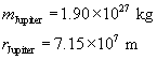
Required
The gravitational field strength at the surface of Mars.
The gravitational field strength at the surface of Jupiter.
Analysis
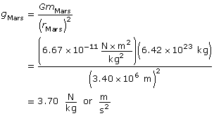
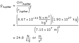
Paraphrase
The gravitational field strength on the surface of Mars is 3.70 N/kg.
SC 4.
Given
Required
The magnitude of the gravitational force acting on the astronaut on Mars and on Jupiter.
Paraphrase
The magnitude of the gravitational force acting on the astronaut on Mars is 390 N.
The magnitude of the gravitational force acting on the astronaut on Jupiter is 2.62 × 10³ N.
SC 5.
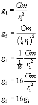
The new gravitational force is 16 times larger than the original force.
1.25. Page 3
Module 3—Electrical Phenomena
Describing Electric Fields

The same theories that you have used with gravitational fields also apply to electric phenomena. After all, if a charged balloon can make strands of hair stand on end without touching them, the balloon must be surrounding itself with an electric field. In this case, the balloon is the source of the field, so it is called the source charge. The individual strands of hair are acting as test bodies, which provide physical evidence that the balloon is surrounded by an electric field.
 Try This: Exploring Electric Field Lines
A simulation will be used to help visualize both the magnitude and direction of the electric field surrounding a single point charge. Consider the large, coloured charge the source charge for the electric field. The small, grey dots represent positive test charges influenced by the field.
You may be required to enter a username and password. Contact your teacher for this information. Open the Electric Field Point Charge simulation.
TR 1. Press the “grid” button (![]() ), and drag the positive charge randomly around the display area. Notice the vector arrows that extend outwards when the charge passes near all the points on the grid. The vector arrows represent the electric field produced by the spherical charge. Sketch the electric field vectors on diagrams like those shown below.
), and drag the positive charge randomly around the display area. Notice the vector arrows that extend outwards when the charge passes near all the points on the grid. The vector arrows represent the electric field produced by the spherical charge. Sketch the electric field vectors on diagrams like those shown below.
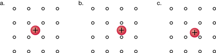
TR 2. In what direction does the electric field always point for a positive source charge?
TR 3. On the simulation, switch the charge to negative by dragging the charge slider (Q) to the left until the charge becomes blue. Sketch the electric field vectors on diagrams like those shown below.
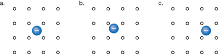
TR 4. In what direction does the electric field always point for a negative source charge?
 Read
Read
 Did You Know?
The symbol for energy is E which is a scalar quantity measured in joules. The symbol for electric field strength is
You can learn more about electric fields and how they differ from gravitational fields by reading “Magnitude and Direction of an Electric Field” on pages 546 and 547 of your textbook.
 Self-Check
SC 6.
- Explain why gravitational field lines are always drawn toward the centre of the source.
- Explain why this simple rule cannot always apply in the case of electric fields.
- Explain how the direction of an electric field vector is determined for a given location outside a source charge.
- State the equation for the electric field. Label each of the variables in this equation.
Self-Check Answers
SC 6.
- Gravitational field lines are always drawn toward the centre of the source because this is the direction of the gravitational force on test masses.
- In the case of electric phenomena, the electrostatic force is not always directed toward the source. Electrostatic forces can attract or repel test charges depending upon the sign of the test charge and the sign of the source charge.
- The direction of an electric field vector is determined by the direction of force on a small positive test charge for a given location outside a source charge.
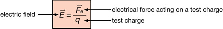
Read
Read “Example 11.1” on page 548 of your textbook. As you go through this example, first identify the key steps and then focus on the details in each step.
SC 7.
Try “Practice Problems” 1 and 2 on page 548 of your textbook.
Self-Check Answers
SC 7. Answer
Page 548 Practice Problem 1
Given
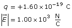
Required
The magnitude of the electrostatic force.
Analysis
Paraphrase
The force is 1.60 × 10⁻¹⁶ C.
Page 548 Practice Problem 2.
Given
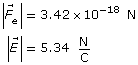
Required
The magnitude of the charge on the small charged sphere.
Analysis
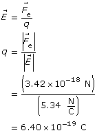
Paraphrase
The magnitude of the charge on the small sphere is 6.40 × 10⁻¹⁹ C.
The magnitude of the electric field at some distance from a point charge can be determined from another equation that is derived from Coulomb’s law. The process of deriving this equation is similar to your earlier work deriving a second equation for gravitational field from Newton’s law of universal gravitation.
Read
To see how this second equation for electric field is derived and applied, read from the bottom of page 548 to the end of “Example 11.2” on page 549 of your textbook. As you go through this derivation, first identify the key steps and then focus on the details in each step. Note how this work parallels your previous practice with gravitational fields.
Try This
TR 5. Calculate and illustrate the electric field strength at a distance of 4.25 × 10⁻¹ m from a +3.00 μC charged particle. Use the simulation to verify your field diagram.
TR 6. Calculate the electric field strength 6.50 × 10⁻² m from a –5.00 μC charged particle. Sketch the electric field lines around the source. Use the simulation to verify the directions of your field lines.
 Module 3: Lesson 4 Assignment
Remember to submit the answer to A 1 and A 2 to your teacher as part of your Module 3: Lesson 4 Assignment.
A 1. Calculate and illustrate the electric field strength at a distance of 8.25 m from a +6.50 μC charged particle. Use the simulation to verify your field diagram.
A 2. Calculate how far from a –5.00 μC charged particle the electric field strength 7.2 × 10⁷ N/C is toward the charge.
1.26. Page 4
Module 3—Electrical Phenomena
Lightning and Earth’s Electric Field

© Brandon Poleski/shutterstock
Each day, there are about 45 000 thunderstorms worldwide. Earth has acquired a net charge from the lightning strikes and therefore surrounds itself with a weak electric field.
Investigations of this phenomenon indicate that, near the surface, Earth’s electric field is typically 150 N/C directed straight down toward the centre of the planet. When the field is constant, the field lines are evenly spaced, as indicated in this diagram.
Under the right circumstances, a tiny, charged droplet of water could be suspended in Earth’s electric field. In this circumstance, the electrostatic effects counteract the effects of gravity, so the drop would no longer be accelerating toward Earth’s surface.
You have the tools to analyze this situation, but you have to be careful to use the equations for electric field correctly. It is important to remember that one equation deals with the charge on a test body, while the other equation deals with the charge on the source of the electric field.

 Self-Check
SC 8. Use the diagram of Earth’s electric field to determine the sign of the net charge on Earth.
Self-Check Answer
SC 8. The diagram of Earth’s electric field shows the field lines directed toward the surface of the planet. This indicates that Earth has a net negative charge. The reason is that electric field lines always point toward a negatively charged source. This is because electric field lines always show the way a positive test charge is forced. So if a positive test charge is attracted toward Earth, the planet must have a net negative charge.
The Vector Addition of Electric Fields
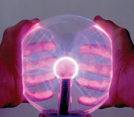
© Image courtsey of Shutterstock.com
St. Elmo’s fire is very difficult to photograph; a camera does not detect the faint blue glow very well, and St. Elmo’s fire occurs in circumstances that make photography difficult. A photographer would have to be close to the top of a ship’s mast in a thunderstorm or just behind the trailing edge of an aircraft wing in flight!
An alternative approach is to photograph a phenomenon that is similar to St. Elmo’s fire. Strictly speaking, the blue streamers of light visible in the photo of this plasma lamp are not St. Elmo’s fire. Nevertheless, the ribbons of light in a plasma lamp do have many things in common with St. Elmo’s fire:
- The effects are due to the presence of strong electric fields.
- The electric fields strip some electrons from gaseous molecules producing a hot, ionized gas called plasma.
- Light is emitted when electrons drop to lower energy levels within atoms.
- The colour of the emitted light depends upon the particular atoms affected.
© Sarah Harland/shutterstock
Since the atmosphere is comprised mostly of nitrogen, the light emitted from St. Elmo’s fire is blue, which is the characteristic colour emitted when nitrogen atoms are ionized. The manufacturers of plasma lamps deliberately introduce other gases to produce dramatic effects.

© ErickN/shutterstock
The streamers of light in this close-up photograph of a plasma lamp are particularly beautiful, not only because the colour is so striking but also because of the graceful, twisting shapes. These shapes are caused by charged particles within the streamers that are under the influence of more than one electric field. St. Elmo’s fire also involves overlapping electric fields that simultaneously influence many charges.
 Read
Read
To see what happens when electric fields with only x components overlap, read from the bottom of page 549 to the end of “Example 11.3” on page 550 of your textbook. As you read through this example, first identify the key steps and then focus on the details in each step.
Self-Check
SC 9. Refer to the previous photos of the plasma lamp. Simplify the situation and suppose that the charged particles within the streamer were only under the influence of the electric field of the negatively charged central orb. If this simplification were true, what shape would the streamers have?
SC 10. Try “Practice Problems” 1 and 2 on page 550 of your textbook. For question 2 remember the charge on a proton and electron is equal to the elementary charge on your datasheet.
Self-Check Answer
SC 9. If the negatively charged central orb was the only source of electric fields, then the electric field lines would be straight—pointing to the centre of the source. Positive ions would be forced to move along these lines and would be attracted to the source, while electrons would be forced to move along these lines to the outside. In this simplified approach, it follows that the streamers would form straight lines, radiating out from the centre.
SC 10.
Page 550 Practice Problem 1
Given
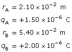
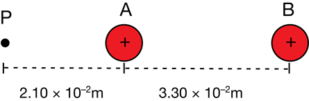
Required
The electric field strength at point P.
Analysis and solution

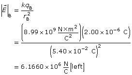
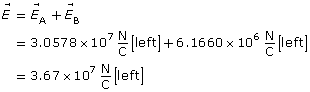
Paraphrase
The electric field at point P is 3.67×10⁷ N/C [left].
Page 540 Practice Problem 2
Given
Required
The electric field halfway between the electron and proton.
Analysis and solution
Since the magnitude of the charge of the electron and proton is the same, and the distance from each particle to the point is the same, the magnitude of the electric field due to the electron and the proton will be the same.
Since the charge on the electron is negative, the electric field caused by the electron will be toward the electron. Since the charge on the proton is positive, the electric field caused by the proton will also be toward the electron.
Paraphrase
The resultant electric field is 4.11×10¹² N/C [toward the electron].
Read
To see what happens when electric fields are described with both x and y components, read “Example 11.4” on pages 551 and 552 of your textbook. As you read through this example, first identify the key steps and then focus on the details in each step.
Self-Check
SC 11. Do “Practice Problem” 1 on page 551 of your textbook.
Self-Check Answer
SC 11.
Given
q1 = +2.00 C
q2 = +2.00 C
r1 = 0.100 m
r2 = 0.100 m
Required
The electric field at point P.
Analysis and Solution
Since q1 and r1 are the same magnitude as q2 and r2, the magnitude of the electric fields will be the same; however, the directions will be different.
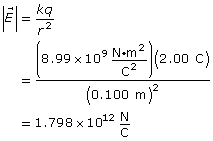
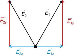
Note that the x components of electric field one and electric field two are in opposite directions but have equal magnitude. Therefore the two cancel each other out.
The resultant electric field at point P is the sum of the y components.
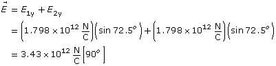
Paraphrase
The electric field at point P is 3.43×10¹² N/C [90°].
 Module 3: Lesson 4 Assignment
Remember to submit the answer to A 3 and A 4 to your teacher as part of your Module 3: Lesson 4 Assignment.
A 3. Point P is collinear with a +2.80 μC and a −8.50 μC as shown in the following diagram. Point P is 10 cm to the left of the positive charge and 20 cm to the left of the negative charge. What is the electric field at point P?
![]()
A 4. The following diagram shows two charged spheres arranged to the left of a point in space labelled P. Use the information on the diagram to calculate the magnitude and direction of the net electric field at point P.
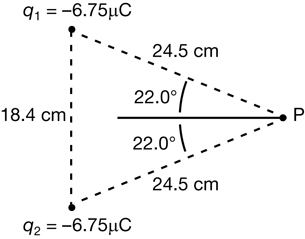
1.27. Page 5
Module 3—Electrical Phenomena
Electric Field Lines in Nature
St. Elmo’s fire is not the only natural phenomenon that is explained using electric field lines. Sharks are capable of detecting the weak electric fields that other animals produce through their muscle activity. This ability enables sharks to detect prey that has buried itself under shallow sand on the seabed.
Just as a source mass surrounds itself with gravitational field lines, a source charge surrounds itself with electric field lines. Since muscle activity is triggered by the moving charges in nerve cells, muscle contractions produce electric fields. In this case, the source charges are very weak, so the resulting electric fields are also very weak.

© Ian Scott/shutterstock
Hammerhead sharks have sensors located in their snouts that allow this predator to detect very weak electrical fields. The hammerhead shark swims close to the seabed seeking prey that has hidden itself under the sand. The electric field lines produced by the prey can extend up into the water above the sand. As the shark swims past a location where the density of the electric field lines suddenly change, the sensors in the shark’s snout are triggered. The shark uses this information to pinpoint the exact location of its hidden prey.
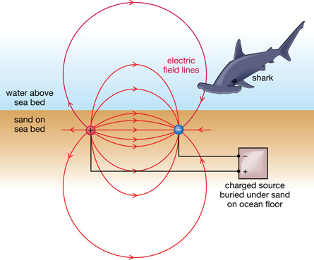
Scientists have verified this ability of sharks by burying pairs of oppositely charged sources in the sand. As the shark swims closer to the sources, the special sensors in its snout detect a change in the density of electric field lines. Where the field lines are most concentrated, the shark disturbs the sand looking for a meal. Astonishingly, this type of behaviour was observed with electric fields as weak as 5 × 10⁻⁷ N/C.
 Read
Read
You can learn more about electric field lines and the patterns they form by reading page 554 of your textbook.
 Self-Check
SC 12.
- Are the field lines in the illustration with the shark drawn in a way that is consistent with the rules for drawing electric field lines listed on page 554 of your textbook?
- Use the rules listed on page 554 of your textbook to identify the location in the illustration where the magnitude of the electric field would be greatest.
- Use your answer to SC 12.b. to identify the location that would likely draw the shark.
Self-Check Answers
SC 12.
- Yes, the field lines are drawn in a way that is consistent with the rules stated in the textbook. Electric field lines start from the positive source and extend radially. Electric field lines terminate at the negative source. The electric field lines are tightly packed between the two sources, indicating that this is where the magnitude of the electric field is greatest.
- The magnitude of the electric field would be greatest where the field lines are densely packed together. This occurs in the region between the two sources but closer to one source or the other.
- Given that the sensors in the shark’s snout are designed to detect changes in the density of electric field lines, these sensors would tend to direct the shark to move into the space between the two charged sources but closer to one source or the other.
Read
Read the instructions in “Minds On: Drawing Electric Field Lines” on page 555 of your textbook.
Self-Check
SC 13. On a sheet of paper, sketch the patterns of the electric field lines shown in each of the situations illustrated in the “Minds On: Drawing Electric Field Lines” activity. Complete each illustration by adding arrowheads to each of the electric field lines.
Self-Check Answers
SC 13.
a. 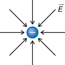
b. 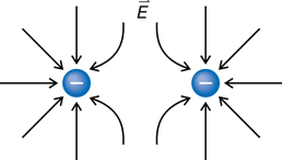
c. 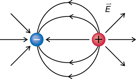
d. 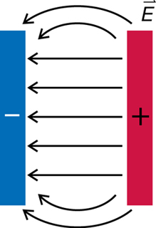
e. 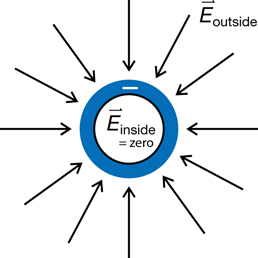
Electric Fields on the Surfaces of Conductors

© Stephen Strathdee/shutterstock
Recall that St. Elmo’s fire has been observed on the wing tips of aircraft that are flying near large concentrations of charge within a thunderstorm. The reason this phenomenon occurs on wing tips, as it does at the ends of other sharply pointed projections, has to do with the distribution of charge on the surface of the aircraft.
As an aircraft flies through thunderclouds, the metal surface of the aircraft can become charged. If electrons are transferred to the aircraft, these excess negative charges will move as far apart as possible due to like charges repelling one another. On a flat metallic surface, the negative charges spread out evenly. So, the resulting pattern of electric field due to these charges is also evenly distributed.
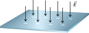
If the same surface is slightly bent, more charges can be added. Can you think why this would be the case? The reason has to do with the fact that charges on opposite sides of the curved surface are unable to repel one another as effectively as they can when the surface is completely flat. On curved surfaces, the electrostatic force that repels each charge away from the others has a component that is no longer parallel to the surface. This means that the parallel component of the force is less and therefore there is less force acting to separate each individual charge away from the others. The result is that the charges can be packed closer together. It follows that the density of the field lines also increases.
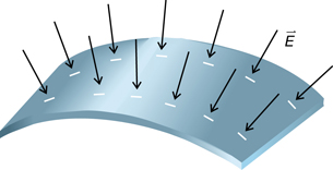
To pack more charges on the surface, and get an even denser pattern of field lines, the same surface could be bent into a more pronounced curve. As the curvature of a given surface increases, so does the capacity of the surface to concentrate charge and produce regions of intense electric fields.
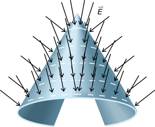
Read
You can learn more about the role of the electrostatic force in explaining the patterns illustrated in the previous diagrams by reading pages 555 to 558 of your textbook. Note the explanation of the electric field inside a hollow conductor as well as the electric field between two charged parallel plates.
Self-Check
SC 14. Record the following diagrams in your notebook. Complete each diagram by sketching the electric field lines within each object.
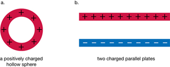
SC 15. Refer to the “infoBIT” in the margin on page 558 of your textbook. Explain the role of the flexible metal shielding in the cable that is used to bring TV signals into a home.
SC 16. Electric fields are a key component of radio waves. Other than convertibles, most vehicles on the roadway can be thought of as metal boxes with holes cut in them for windows. Use this information to explain why the antenna for a vehicle’s radio must be mounted outside of the vehicle or built into the windshield.
Self-Check Answers
SC 14.
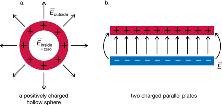
SC 15. The metal shielding prevents electrical and magnetic interference from influencing the TV signals that are transmitted through the cable. The flexible metal shielding effectively surrounds the conductor, encasing the TV signal with a hollow metal covering. Since electric fields within a hollow conductor are zero, there is no unwanted influence on the TV signals transmitted through the cable.
SC 16. If electric fields are a key component of radio waves, then radio waves cannot penetrate the interior space of a vehicle because electric fields inside a hollow conductor are zero. By placing the antenna outside the vehicle or in the windshield, the radio waves do not have to penetrate the metal shell of the vehicle to be detected.
1.28. Page 6
Module 3—Electrical Phenomena
 Reflect and Connect
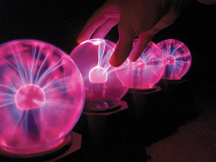
© Katrina Outland/shutterstock
As was mentioned earlier in the lesson, the blue streamers emitted by a plasma lamp have many things in common with St. Elmo’s fire. One key difference is that, within a plasma lamp, the strong electric fields are produced artificially within the glass by the circuitry at the base of the lamp. In the case of St. Elmo’s fire, the strong electric fields are produced naturally at the edges or at the pointed tips of conductors near large concentrations of charge in a thundercloud.
 Discuss
D 1. Use the information presented in this lesson to explain why St. Elmo’s fire is observed at the ends of sharply pointed exterior surfaces of aircraft such as wing tips and propellers. Be sure to explain why St. Elmo’s fire is not observed on surfaces that are flat or on interior parts of the aircraft.
D 2. Post your summary to the discussion area set up by your teacher. Compare your summary to at least one other explanation produced by another student. Identify similarities and differences between your work and the work of other students.
D 3. If you were to update your explanation of St. Elmo’s fire, what changes would you make?
 Module 3: Lesson 4 Assignment
Remember to submit the answer to D 4 to your teacher as part of your Module 3: Lesson 4 Assignment.
D 4. Use your answers to D 1, D 2, and D 3 to revise your explanation of why St. Elmo’s fire occurs on sharply pointed projections of aircraft and not on flat exterior surfaces or interior surfaces.
Discussion Scoring Guide
Principles involved: electric fields, electrostatic forces, conservation of charge |
||||
Criteria |
Level 1 |
Level 2 |
Level 3 |
Level 4 |
Knowledge |
||||
Demonstrates a vague and sometimes incorrect understanding of the physics principles involved. Obvious irrelevant or missing information. |
Demonstrates a basic understanding of the physics principles involved. May exhibit minor mistakes or vague information or application to the situation. |
Demonstrates a good understanding of the physics principles involved and applies them properly to the given situation. All necessary information is given. |
Demonstrates a superior understanding of the physics principles involved and their application to the situation. All applications are considered in detail. |
|
Reflection |
||||
The post shows reflection on one’s own and other students’ work. Contributes to the group discussion. |
Does not make an effort to participate. Seems indifferent to discussion. |
Occasionally makes meaningful reflections on the group’s efforts or discussions. Marginal effort is shown to become involved with the group or discussion. |
Frequently makes meaningful reflections on the group’s efforts and presents relevant viewpoints for consideration by the group. Interacts freely with group members. |
Regularly attempts to motivate the group discussion and delve deeper into concepts. Interacts freely and encourages all group members. |
Content and presentation of discussion summary |
||||
The information is logically arranged in a clear and concise manner. |
The information is poorly organized with many concepts implied. Irrelevant or rambling sentences make reading difficult. |
The information is somewhat organized with implied concepts. Excessive words or awkward sentences are used, which hinder reading. |
The information is well-organized and logically arranged. All concepts are explicitly explained. There are a few awkward but understandable sentences. |
The information is well- organized and very easy to understand. Well-worded sentences make reading pleasurable. |
Module 3: Lesson 4 Assignment
Remember to submit the Module 3: Lesson 4 Assignment to your teacher for marks.
1.29. Page 7
Module 3—Electrical Phenomena
 Lesson Summary
At the beginning of this lesson you were asked the following essential questions:
- What is an electric field, and how can it be described and analyzed?
- What exactly is St. Elmo’s fire, and why does it occur at the end of pointed surfaces?
You have learned that an electric field is the property of space surrounding a source charge that enables the source charge to exert forces on other charges that enter this region. One way to describe electric fields is to use equations:
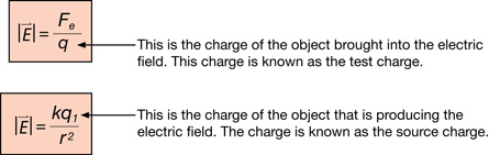
The direction of an electric field is determined by the direction of the electrostatic force experienced by a small positive test charge. This can be used to describe electric fields in terms of patterns of electric field lines around source charges.
St. Elmo’s fire is a consequence of the strong electric fields that develop along the sharp edges and points of conductors. These electric fields are strong enough to ionize molecules of air, leading to the emission of light when free electrons combine with positively charged ions.
Lesson Glossary
electric field: a property of the space around a source charge that enables the source charge to exert forces on test charges in the region
field: a region of influence surrounding an object through which a force operates
1.30. Lesson 5
Module 3—Electrical Phenomena
Lesson 5—Electric Potential Energy
 Get Focused

© Igor Talpalatski/shutterstock
Danger signs are always placed near high-voltage equipment. What makes this equipment so dangerous? Why are high-voltage power lines more dangerous to humans than the 120-volt power lines commonly found in houses and stores?
The truth is that high voltages are, in fact, not always dangerous. For example, when you rub a balloon on your head, you can generate thousands of volts completely safely.
Other devices, such as electric fencing for livestock, operate at tens of thousands of volts yet never cause any permanent damage to livestock that come into contact with it. This is in contrast to the relatively low voltage found in homes, which, as it turns out, is much more dangerous. When is high voltage dangerous? Why?
In this lesson you will explore the following essential questions:
- What is electric potential energy?
- How is electric potential energy similar to gravitational potential energy?
- What is voltage?
- How is voltage calculated?
 Module 3: Lesson 5 Assignments
Your teacher-marked Module 3: Lesson 5 Assignment requires you to submit a response to the following:
-
Lab—LAB 1, LAB 2, LAB 3, LAB 4, LAB 5, LAB 6, LAB 7, LAB 8, and LAB 9
You must decide what to do with the questions that are not marked by the teacher.
Remember that these questions provide you with the practice and feedback that you need to successfully complete this course. You should respond to all the questions and place those answers in your course folder.
1.31. Page 2
Module 3—Electrical Phenomena
 Explore

© Christophe Michot/shutterstock
These BASE (building, antenna, span, earth) jumpers are about to enjoy a “huge dose of adrenaline” as they accelerate toward Earth’s surface before opening their parachutes. When they reach their highest speed, the kinetic energy of the jumpers will be electrifying. What is the source of this vast amount of kinetic energy?
You could say that the peak kinetic energy enjoyed by each jumper on the way down was earned by the work done in the climb on the way up. Recall from previous courses that when work is done to change the position of an object, the system containing the object gains potential energy. In this case, since each jumper does work against the force of gravity, each jumper increases the gravitational potential energy of the “jumper-Earth system” as they climb to the top of the platform.
In previous lessons, you have seen many similarities between the gravitational field and the electric field. It’s natural to wonder if a charged object could store potential energy by doing work in an electric field, similar to the way that the BASE jumpers stored potential energy by doing work in a gravitational field.
You will have an opportunity to solve this problem in the next lab activity.
1.32. Page 3
Module 3—Electrical Phenomena
 Lesson 5 Lab: Storing Energy in Non-Uniform Electric Fields
There are two parts to this Lab activity. The first part is a simulation that examines how a charged particle behaves in a non-uniform electric field due to the force caused by the field. The second part is a simulation that examines the energy transfer from kinetic energy and potential energy between the charged particle and the non-uniform electric field.
Part A: Motion in a Non-Uniform Electric Field
Purpose
In this part of the lab activity you will use a computer simulation to collect data enabling you to answer the following questions:
- How does a test charge move in a non-uniform electric field?
- How can this motion be explained using physics principles?
Procedure
Step 1: You may be required to enter a username and password. Contact your teacher for this information. Open the Electrical Field Potential, Non-Uniform simulation, and enter the following settings:
- Reset the simulation (
 ). Note that the source is the larger charge on the left and the test body is the smaller charge on the right.
- Turn on the grid (
 ).
).
- Click on the “velocity mode” button (
 ) until the velocity is displayed in the polar method (
 ), showing a velocity in m/s and a direction in degrees.
- Drag the test charge to the following location: (x,y) = (100,0).
- Click on the “initial” button (
 ) to have this position be the point where initial values are determined.
- Note that if you use the “rewind” button (
 ), you can return to these initial settings at any time during this lab activity. However, if you choose to reset (), you will have to re-enter all these initial settings.
If these settings have been applied, the screen should look like this.
Step 2: Collect the following data from the screen, which you will use in the Analysis:
qsource= __________ qtest= ____________
mtest= ___________
Step 3: Press “play” (![]() ), and observe the motion of the test charge until it reaches the point (x,y) = (300,0). Then press the “pause” button (
), and observe the motion of the test charge until it reaches the point (x,y) = (300,0). Then press the “pause” button (![]() ). Record the final velocity for the particle once it has reached this point. You will use this value in the Analysis.
). Record the final velocity for the particle once it has reached this point. You will use this value in the Analysis.
![]() = ___________
= ___________
Analysis
 Self-Check
SC 1.
- Describe the motion of the test charge as it moved from (100,0) to (300,0).
- Explain the motion of the particle using Newton’s laws of motion.
- Draw a free-body diagram to show the force acting on the particle at the points (100,0) and (300,0).
- Explain how the source charge was able to exert a force on the test charge even though the particles were not touching.
SC 2.
- Calculate the magnitude and direction of the electric field of the source charge at the locations (100,0) and (300,0).
- Explain how your answers to the previous question demonstrate that electric field varies inversely to the square of the distance from the source.
SC 3.
- Use your values for electric field from SC 2.a. to calculate the magnitude and direction of the electrostatic force acting on the test charge at the locations (100,0) and (300,0).
- Use your answers from SC 3.a. to calculate the acceleration of the test body at the locations (100,0) and (300,0).
Self-Check Answers
SC 1.
- Since the velocity is increasing, the motion of the test charge is accelerated motion.
- The electrostatic force acting on the test charge pushes the test charge away from the source charge since both objects are positively charged. The electrostatic force is the only force acting on the particle; therefore, this force is an unbalanced force. According to Newton’s second law of motion, unbalanced forces cause objects to accelerate in the direction of the unbalanced force.
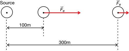
- The electric field of the source charge enabled it to exert a force on the test charge even though these charges were not touching.
SC 2.
a.
Given
Required
The electric field at 100 m, ![]() , and the electric field at 300 m,
, and the electric field at 300 m, ![]()
Analysis and Solution
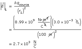

Since the source is positive, both electric field vectors are directed away from the source at an angle of 0°.
Paraphrase
- The electric field at the location 100 m to the right of the source is
 [0°].
[0°].
The electric field at the location 300 m to the right of the source is [0°].
[0°].
- The location that is 300 m from the source is three times further away than the location that is 100 m from the source. Therefore, the magnitude of the electric field is only
 as strong at the further location, compared to the closer location.
SC 3.
a.
Given
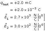
Required
The electrostatic force acting on the test charge at 100 m and at 300 m.
Analysis and Solution
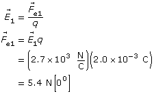
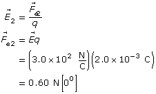
Paraphrase
- The electrostatic force on the test charge at (100,0) is 5.4 N [0°] and at (300,0) it is 0.60 N [0°].
b.
Given
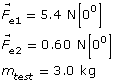
Required
The acceleration of the test charge at 100 m and at 300 m.
Analysis and Solution
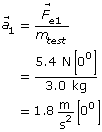
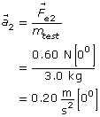
Paraphrase
The acceleration of the test charge at 100 m is 1.8 m/s2 [0°] and at 300 m it is 0.20 m/s2 [0°].
Part A Conclusion
 Module 3: Lesson 5 Assignment
Remember to submit the answers to LAB 1 and LAB 2 to your teacher as part of your Module 3: Lesson 5 Assignment.
LAB 1. Describe the motion of a test charge in a non-uniform electric field.
LAB 2. Explain the motion of a test charge in a non-uniform electric field.
1.33. Page 4
Module 3—Electrical Phenomena
Part B: Storing Potential Energy in a Non-Uniform Electric Field
Purpose
In this part of the lab activity you will continue to use electric field potential, non-uniform simulation to collect data enabling you to answer the following question:
- In which direction must a test charge be moved within an electric field if potential energy is to be stored in the system?
Procedure
Step 1: If you still have the computer simulation open from Part A of this lab activity, continue with the next step. If you need to re-open the simulation, you will need to enter the settings described in Part A.
Step 2: To return the particle to its initial position, (100,0), press “rewind” (![]() ). Press “data” (
). Press “data” (![]() ) to view a data chart describing the particle, as well as a set of bar graphs of potential energy (in blue), kinetic energy (in red), and voltage (in yellow).
) to view a data chart describing the particle, as well as a set of bar graphs of potential energy (in blue), kinetic energy (in red), and voltage (in yellow).
If these settings have been applied the screen should look like these settings:
Step 3: Press “play” (![]() ), and observe the changing energy values until the test charge reaches the point (x,y) = (300,0). Then press “pause” (
), and observe the changing energy values until the test charge reaches the point (x,y) = (300,0). Then press “pause” (![]() ). You may simply press “rewind” (
). You may simply press “rewind” (![]() ) to return the test charge to its starting position if you need to try again. Collect the following data, which you will use in the Analysis, for these two locations:
) to return the test charge to its starting position if you need to try again. Collect the following data, which you will use in the Analysis, for these two locations:
Data for the Test Charge at (100,0) |
Data for the Test Charge at (300,0) |
Kinetic Energy = Ek = |
Kinetic Energy = Ek= |
Potential Energy = Ep = |
Potential Energy = Ep= |
Total Energy = Etotal = |
Total Energy = Etotall = |
Step 4: Even though you will be properly introduced to voltage later in this lesson, this is a good opportunity to gather voltage data from the simulation. You will use this voltage data in the Analysis. Collect the following additional data for these two locations:
Data for the Test Charge at (100,0) |
Data for the Test Charge at (300,0) |
Potential Energy = Ep = |
Potential Energy = Ep = |
Test Charge = qtest = |
Test Charge = qtest= |
Voltage = V = |
Voltage = V = |
Step 5: Return the particle to its initial position, (100,0), by pressing “rewind” (![]() ). Enter the highest value of initial velocity that the simulation will accept, 30.0 m/s. Press “play” (
). Enter the highest value of initial velocity that the simulation will accept, 30.0 m/s. Press “play” (![]() ), and let the simulation run in the background while you answer the next three questions.
), and let the simulation run in the background while you answer the next three questions.
Analysis
 Self-Check
SC 4.
- As the test charge moves from (100,0) to (300,0), calculate the change in the potential energy, kinetic energy, and the total energy.
- Identify the physics principle that explains your results in SC 4.a.
SC 5. If the test charge were to be moved toward the source from (300,0) to (100,0) work would have to be done. The applied force would have to overcome the electrostatic force at each point between (300,0) and (100,0).
- Explain the difficulties in using the equation
 to solve for the work in this case.
- Use the idea that the potential energy is equal to the work done to change the position of an object to solve for the work in this case.
SC 6. Press “pause” (![]() ), and record the following values:
), and record the following values:
- position of the test charge: (x,y) = (________ m, __________ m)
- potential energy of the system = ____________
The simulation does not display potential energy values less than 1 J. If the system could display values of potential energy that were in millijoules or even in microjoules, you would be waiting forever for the potential energy of the system to reach zero. That’s because potential energy is defined to be zero at infinity—it takes an infinitely long time for a particle to move infinitely far away. Speculate on why infinity was chosen as the reference point having zero potential energy for this system.
Self-Check Answers
SC 4.
a.
| Initial Energy Values at (100,0) | Final Energy Values at (300,0) | Change in Energy Values (ΔE = Ef – Ei ) |
|---|---|---|
Ek = 338 J |
Ek = 697 J |
ΔEk = 359 J |
Ep = 539 J |
Ep = 180 J |
ΔEp = –359 J |
Etotal = 877J |
Etotal = 877 J |
ΔEtotal = 0 |
b. The results in the previous answer can be explained using the law of conservation of energy. The gain in the kinetic energy of the test charge accounted for by the loss of an identical amount of potential energy.
SC 5.
- The difficulty with this equation is that the value for the applied force changes continually to match the continual changes in the electrostatic force. The electrostatic force would increase as the test charge moves closer to the source charge.
Given
The location (300,0) is the initial position.
The location (100,0) is the final position.

Required
The work done to move the charge from 300 m to 100 m.
Analysis and Solution
The change in the potential energy of the system is equal to the work done to change the position of the test charge.
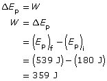
Paraphrase
The work done to move the test charge from 300 m to 100 m is 359 J.
SC 6. The data you collected for the position of the test charge and the potential energy will vary depending on how long you let the simulation run. Your data should reflect a large separation between the test charge and the source charge of the field. That is, you should have observed a large value of x in the test-charge position (x, y). The y value should not change much, if at all, from 0.
The potential energy you record should be close to, or possibly equal to, 0 J.
There is good reason for choosing infinity as the reference point having zero potential energy. This reference point works for virtually all charges in virtually all circumstances, even if the system being studied has more than one source charge. If some other reference point were chosen as a reference point, such as the surface of a source charge, then you’d have to choose which source charge would provide the reference point for the system.
Part B Conclusion
 Module 3: Lesson 5 Assignment
Remember to submit the answer to LAB 3 to your teacher as part of your Module 3: Lesson 5 Assignment.
LAB 3. In which direction must a test charge be moved within an electric field if potential energy is to be stored in the system? Why?
1.34. Page 5
Module 3—Electrical Phenomena
Storing and Releasing Potential Energy

© Vasily Smirnov/shutterstock (jumper)
Both of these photos show objects accelerating in fields. The BASE jumper is accelerating to Earth due to the force of gravity acting through Earth’s gravitational field. The charged soap bubbles are accelerating away from the charged globe of the Van de Graaff generator due to the electrostatic force acting through the electric field of the Van de Graaff generator. In both cases, potential energy stored in the system is being transformed into kinetic energy.
 Read
Read
You can find out more about the similarities between the potential energy stored in these two situations by reading pages 560 to 562 of your textbook. Pay special attention to “Example 11.5” and to the connections to the previous lab activity.
 Self-Check
SC 7.
- Define electric potential energy.
- Solve “Practice Problem” 2 on page 561 of your textbook.
- Explain why it is important to indicate the reference position when stating a value for potential energy.
SC 8. When it comes to calculations, the textbook uses a particular method for defining the reference point for electric potential energy. Describe this method, and relate it to your experiences with the simulation in the previous lab activity.
Self-Check Answers
SC 7.
- Electric potential energy is the energy stored in a system when work is done to move a charge from one location to another.
Given
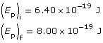
Required
The work necessary to move the charge.
Analysis and Solution
Paraphrase
The work to move the charge is 1.60×10⁻¹⁹ J.
- Potential energy is equal to the work done to change the position of an object. This only makes sense if you know the reference level where potential energy is defined to be zero. The reference level is the starting point for the displacement vector in the work calculation.
SC 8. The textbook uses the method where electric potential energy is defined to be zero at infinity. In other words, infinity is the reference level. When the simulation was allowed to run for nearly 20 minutes, the potential energy of the system dropped to a value of 1 J when the distance from the source was very large. It appears that the simulation uses the same method of defining the electric potential energy to be zero at infinity
Electric Potential or Voltage
The following diagram summarizes some of the key findings from the previous lab investigation.
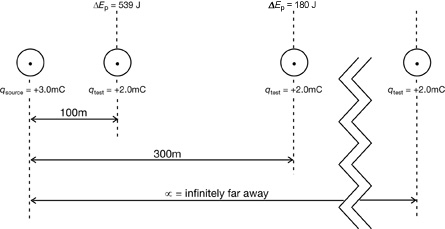
It takes 180 J of work to move a positive test charge from a point infinitely far away to a location 300 m from the source charge. Since this work was done against the electric field, the electric potential energy of the system is 180 J at this point. Note that electric potential energy is defined to be zero at infinity.
It takes even more work, 539 J, to move the same positive test charge from a point infinitely far away to a location 100 m from the source charge. The electric potential energy of the system is said to be 539 J at this point.
voltage: the value, in volts, of the change in electric potential energy stored per unit of charge.
It is also called electric potential or potential difference.
Although this system accurately describes the situation, it is impractical to make these sorts of measurements in practice. Measuring the work done moving tiny particles with minute amounts of charge is a problem. A more practical way to describe these situations is to use a new quantity called voltage (or electric potential).
Expressed as an equation,
![]()
Quantity |
Symbol |
SI Unit |
change in electric potential energy |
ΔEp |
J |
charge |
q |
C |
voltage or |
V |
V |
Note that 1 volt is the electrical potential at a given point in an electric field such that 1 joule of energy is required to move 1 coulomb of charge from infinity to that point.
1 V = 1 J/C
 Try This
TR 1. The volt is not a base SI unit. Break the volt down into C, kg, m, and s.
The following graphic illustrates how the voltage would be calculated for the results of the previous lab activity:
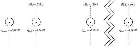
The number of volts describes the amount of energy required to move a coulomb from infinity to each location in the field—a value of “90 000 volts” means “90 000 joules per coulomb.”
Self-Check
SC 9. Suppose the test charge shown in the previous diagram was +4.0 mC instead of +2.0 mC.
- Explain how this new value for the test charge would affect the amount of work required to move the test from infinity to each location.
- Given your answer from SC 9.a., explain how this new value for test charge would affect the value of the voltage at each location.
- Does the value of the voltage depend upon the value of the test charge?
Self-Check Answer
SC 9.
- If the charge on the test body were doubled, then it would take twice as much work to move the test body from infinity to each location. Even though the displacement values would remain unchanged, doubling the charge would double the electrostatic force, which would double the amount of work required.
- Voltage is the change in electrical potential energy per unit of charge. Doubling the charge also doubles the electrical potential energy stored in the system since the work done on the charge doubles. The overall effect is that the voltage would be unchanged.
- No, the value of the voltage is independent of the charge. This is demonstrated in the answer to SC 9.b.
1.35. Page 6
Module 3—Electrical Phenomena
 Lesson 5 Lab: Electric Potential as a Function of Distance
Background Information
In the previous lab activity you collected data for a positive test charge that was forced to move in the electric field of a positive source charge. As the test charge was moved closer to the source charge, work was done and potential energy was stored in the system. Since the potential energy increased, the electric potential also increased as the test charge was brought closer to the source.
In the analysis of this system, it was noted that the electric field of the source and the electrostatic force exerted on the test charge both varied as the inverse of the distance squared from the source. Do you think that the electric potential also varies as the inverse square of the distance of separation?
Purpose
In this lab activity you will design an experiment and collect data to answer the following question:
- Does the electric potential between a source charge and a test charge vary as the inverse square of the distance of separation?
You may be required to enter a username and password. Contact your teacher for this information. You will use the capabilities of the Electric Field Potential, Non-Uniform simulation as a tool to gather the necessary data. Make the initial settings of the simulation identical to those used in the previous investigation.
In this set-up, you can collect data along the x-axis from 100 m to 600 m.
 Module 3: Lesson 5 Assignment
Remember to submit the answers to LAB 4, LAB 5, and LAB 6 to your teacher as part of your Module 3: Lesson 5 Assignment.
LAB 4. Does the electric potential between a source charge and a test charge vary as the inverse square of the distance of separation? Describe a procedure that would enable you to collect the necessary data to answer this question.
LAB 5. Collect the necessary data, according to the steps of the procedure that you described in LAB 4.
LAB 6. Analyze the data that you collected so that you can answer the question posed in LAB 4.
1.36. Page 7
Module 3—Electrical Phenomena
Potential Difference
© Yury Asotov/shutterstock
Electronic technicians complete a number of tasks when assembling circuit boards. A voltmeter is frequently used when testing circuits. The word voltage stems from the fact that potential difference is measured in volts with a voltmeter.
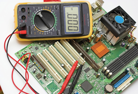
© Ovidiu Iordachi/shutterstock
In these cases, the voltage is describing the amount of work required per unit of charge to move a test charge from one point to another within a circuit. Since the calculation involves subtracting one potential value from another, this quantity is called electric potential difference (or just potential difference for short).
electric potential difference: the change in electric potential experienced by a charge moving from one point to another in an electric field.
It is sometimes called potential difference.
In terms of an equation, electric potential difference is described as
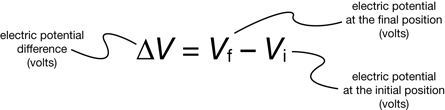
The following calculation shows how to calculate the electric potential difference if the test charge in the previous lab activity was moved from an initial location 300 m from the source to a final location 100 m from the source.
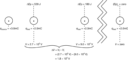
 Read
Read
You can find out more about voltage by reading the sections called “Electric Potential” and “Electric Potential Difference” on pages 563 to 566 of your textbook. Pay close attention to the explanation of the electron volt and to “Example 11.8.”
 Self-Check
SC 10.An electron is accelerated to high velocities within the picture tube of an old-style CRT (cathode ray tube) computer monitor. The potential difference used in the picture tube is 375 V.
- The charge of an electron is 1.60 × 10⁻¹⁹ C. Calculate the energy gained by the electron in joules.
- Calculate the energy gained by the electron in electron volts.
- Consider your answers to SC 10.a. and SC 10.b. Suggest a reason why the electron volt is considered to be a convenient unit for researchers studying the behaviour of electrons and other particles in electric fields.
SC 11. a. Complete “Practice Problem” 2 on page 566 of your textbook.
- Use your answer from SC 11.a. to determine the final velocity of the electron assuming that it started at 8.00×10⁷ m/s. Remember that you can find the mass of the electron on your data sheet.
Self-Check Answers
SC 10.
Given
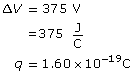
Required
The gain in energy of the electrons.
Analysis and Solution
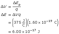
Paraphrase
The electrons gain 6.00×10⁻¹⁷ J.
Method 1
Given
The energy was calculated as Joules in SC 10.a.
ΔE = 6.00×10⁻¹⁷ J
1eV = 1.60×10⁻¹⁹ J
The conversion fraction is on the physics data sheet.
Required
The energy in electron volts.
Analysis and Solution
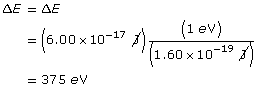
Paraphrase
The electron gains 375 eV.
Method 2
Given
ΔV = 375 V
q = 1e
Required
The energy in electron volts.
Analysis and Solution
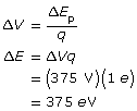
Note 1 e (1 elementary charge) is an exact value, therefore does not count for significant digits.
Paraphrase
The electron gains 375 eV.
The answer to the previous question labelled “Method 2” simply requires multiplying the value of the potential difference in volts by the charge of 1 electron. In this case, if an electron is accelerated through 375 V the energy gained is 375 eV. What could be easier?
SC 11.
Given
ΔV = 4.00×10⁴ V
q = 1.60×10⁻¹⁹ C
Required
The energy of the electron in Joules and electron volts
Analysis and Solution
Since the electron has been accelerated by 4.00×10⁴ V, the energy it has gained is 4.00×10⁴ eV.
An energy value in Joules can be determined using the equation or by unit conversion.
Equation
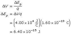
Unit Conversion
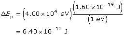
Paraphrase
The electron gains 4.00×10⁴ eV or 6.40×10⁻¹⁵ J of energy.
Given
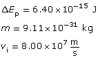
Required
The final velocity of the electron.
Analysis and Solution
Using the conservation of energy, the energy gained by the electron will be converted into kinetic energy.
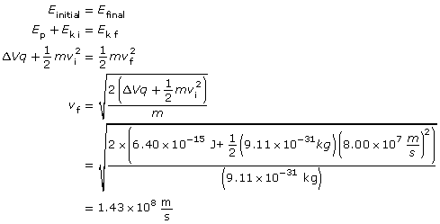
Paraphrase
The final velocity of the electron is 1.43×10⁸ m/s.
1.37. Page 8
Module 3—Electrical Phenomena
 Lesson 5 Lab: Storing Energy in Uniform Electric Fields
Purpose
In this lab activity you will use a computer simulation to collect data enabling you to answer the following questions:
- How does a test charge move in a uniform electric field?
- How can this motion be explained using physics principles?
Procedure
Step 1: You may be required to enter a username and password. Contact your teacher for this information. Open the Electric Field Potential, Uniform simulation, and enter the following settings:
- Reset the simulation (
 ). Note that in this simulation the electric field is not varying as it is in the region surrounding a single point charge. The electric field in this simulation is uniform in strength and direction once the “play” button (
 ) is pressed.
- Turn on the grid (
 ).
).
- Click on the “mode” button (
 ) for both the electric field and velocity until both of these quantities are displayed in the polar method (
 ), showing a direction in degrees.
- Enter the following values for the electric field: 10.0 V/m at 0°. (Note that the unit for field used here, the volt per metre, is equivalent to a newton per coulomb. You’ll learn more about this later in the lesson.)
- Click on the vectors button, and turn on the electric field vector from the “Visible Vectors” option box.
- Enter the following values for the initial velocity: 5.0 m/s at 0°.
- Drag the test charge (red dot) to the following location: (x,y) = (100,0).
- Click on the “initial position” button (
 ) to have this position be the point where initial values are determined.
- If you choose to rewind (
 ), you can return to these initial settings at any time during this lab activity. However, if you use the “reset” button (), you would have to re-enter all these initial settings.
If these settings have been applied, the screen should look like these settings.
Step 2: For the Analysis, you will need to collect the following data from the screen:
![]() = __________
= __________ ![]() = ____________
= ____________
qtest = ___________ mtest = _____________
Step 3: Press play (![]() ), and observe the motion of the test charge until it reaches the point (x,y) = (300,0). Then press the “pause” button (
), and observe the motion of the test charge until it reaches the point (x,y) = (300,0). Then press the “pause” button (![]() ). Use “rewind” (
). Use “rewind” (![]() ) if it takes several attempts to get this right. Record the final velocity for the particle once it has reached (300,0). You will use this value for the Analysis.
) if it takes several attempts to get this right. Record the final velocity for the particle once it has reached (300,0). You will use this value for the Analysis.
![]() = ___________
= ___________
Analysis
 Self Check
SC 12.
- Calculate the magnitude and direction of the electrostatic force acting on the test charge at the locations (100,0) and (300,0).
- Draw a free-body diagram to show the force acting on the particle at the points (100,0) and (300,0).
- Refer to your answer to SC 12.b. How is this free-body diagram different from the one that you drew in the previous lab activity when the electric field was non-uniform?
- Use your values for electrostatic force to calculate the acceleration of the test charge at the locations (100,0) and (300,0).
Self Check Answers
SC 12.
a.
Given
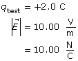
Required
The magnitude and direction of the electrostatic force at 100 m and 300 m, ![]()
Analysis and Solution
- The electric field is directed from left to right, so the electrostatic force acting on a positive test charge will also be from left to right.
- The electric field has the same magnitude in both locations, so the magnitude of the electrostatic force will be the same in both locations for a given test charge.
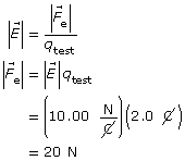
Paraphrase
The electrostatic force will be 20 N [right] in both locations.
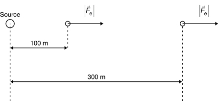
- When the electric field is uniform, the electrostatic force vectors have the same magnitude and direction in all locations. This stands in contrast to the situation in the previous lab activity where the electrostatic force vectors decreased in magnitude as the distance increased from the source.
Given

Required
The acceleration of the test charge at 100 m and at 300 m.
Analysis and Solution
The acceleration will be the same at both locations because the electrostatic force is the same at each location.
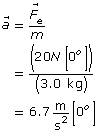
Paraphrase
The acceleration of the text charge is 6.7 m/s2 [0°] at both 100 m and 300 m.
Conclusion
 Module 3: Lesson 5 Assignment
Remember to submit the answer to LAB 7 to your teacher as part of your Module 3: Lesson 5 Assignment.
LAB 7. Describe the motion of a test charge in a uniform electric field.
LAB 8. Explain the motion of a test charge in a uniform electric field.
LAB 9. Explain why the equation ![]() cannot be applied in this situation.
cannot be applied in this situation.
1.38. Page 9
Module 3—Electrical Phenomena
The Electric Field Between Charged Plates

© Lisa F. Young/shutterstock
Many graphic artists prefer to use the old-style CRT monitors because these monitors often give a truer representation of colours than LCD monitors.
The key component of a CRT monitor is the picture tube, which uses two oppositely charged parallel plates to accelerate a beam of electrons toward the screen. When the electrons hit the phosphor coatings on the inside of the screen, many colours of light are produced. Controlling the voltage regulates the electric field between the parallel plates in the picture tube. How does the voltage across two parallel plates relate to the strength of the electric field between those plates?
 Read
Read
To learn how potential difference can be used to develop a new equation describing the electric field between parallel plates, read pages 567 and 568 of your textbook.
 Self-Check
SC 13. Produce a flowchart to show how potential difference can be used to derive a new equation describing the electric field between charged plates.
SC 14. Complete a unit analysis to show that one volt per metre is equivalent to one newton per coulomb.
SC 15. Complete “Practice Problem” 2 on page 568 of your textbook.
Self-Check Answers
SC 13. Here is one possible flow chart showing the derivation.
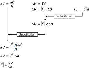
SC 14.
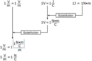
SC 15.
Given
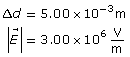
Required
The voltage across the spark plug’s electrodes.
Analysis and Solution
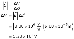
Paraphrase
The voltage across the electrodes is 1.50×10⁴ V.
 Try This

© Yury Asotov/shutterstock
Researchers in a physics lab were experimenting with charged particles moving between parallel plates. In the course of their research, they decided to modify the apparatus to increase the strength of the electric field between the two plates.
The researchers doubled the potential difference across the plates and then reduced the separation of the plates to a third of its original value. As the following analysis with ratios demonstrates, the final arrangement of the apparatus resulted in producing an electric field that was six times stronger than the electric field in the initial arrangement of the apparatus.
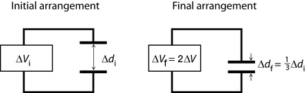
Try This
TR 2. Suppose the researchers made further modifications to the apparatus. This time, they made the potential difference across the plates four times larger than the initial apparatus and they reduced the separation of the plates to a fifth of the initial value. Use a ratio analysis to determine how the electric field strength in this final arrangement compares to the electric field strength in the initial arrangement.
1.39. Page 10
Module 3—Electrical Phenomena
 Reflect and Connect
Now that you have a better understanding of voltage, you should be able to explain some of the statements that were made in Get Focused.
SC 16. Explain the following statement: “When you rub a balloon on your head, you can generate thousands of volts completely safely.”
 Self-Check Answer
SC 16. The explanation has to do with the equation for potential difference.
![]() ; therefore,
; therefore,
ΔEp = ΔVq
The electric potential energy that is available to do work will be low when only a very small amount of charge (q) experiences the relatively high potential difference (ΔV). Rubbing a balloon on your head does exactly this—it produces a very high voltage for very, very few charges. So when the balloon “discharges,” the amount of energy is very small and harmless.
In general, sources of voltage are dangerous when large numbers of charges are involved because the energy is transferred through the motion of the charges. High-voltage power lines are certainly in this category because large numbers of charges have been given huge amounts of energy. It is not unusual for some power lines to operate at 250 kV. This combination of extremely high voltage with a huge number of charges makes these structures particularly dangerous. It’s important to have a comprehensive safety program when working near high-voltage power lines that conduct significant amounts of charge and energy.
© Stephen Finn/shutterstock
© Epcor Utilities Inc.
 Module 3: Lesson 5 Assignment
Remember to submit your Module 3: Lesson 5 Assignment to your teacher.
1.40. Page 11
Module 3—Electrical Phenomena
 Lesson Summary
At the beginning of this lesson you were asked the following essential questions:
- What is electric potential energy? How is it similar to gravitational potential energy?
- What is voltage? How is voltage calculated?
Both electric potential energy and gravitational potential energy result when work is done to move an object in a field. In both cases, work is done by applying an external force on the object that is opposite to the force that the field would exert on the object. Gravitational potential energy can be increased when a mass is moved up, away from Earth’s surface, parallel to the gravitational field. Electric potential energy can be gained by moving a positive charge toward a positive source, or by moving a negative charge away from a positive source. In both cases, the distance moved is parallel to the electric field.
While potential energy is measured in joules, electric potential is measured in volts. A volt is a joule per coulomb because electric potential is the change in electric potential energy stored per unit of charge. Many people prefer to use the term voltage for electric potential because it reminds them how this quantity is measured. In most applications, potential difference is used instead of electric potential because the change in energy stored per charge is measured relative to some other point in the electric field rather than using infinity as the reference point.
Dangers associated with high voltage increase with increasing amounts of charge. At very high voltages, the amount of energy per unit of charge is high, but the total amount of electrical energy can be limited by having few charges held at this voltage. In the case of high-voltage power lines, the product of high energy per unit of charge and the high number of charges can lead to electrocution and death.
Lesson Glossary
electric potential difference: the change in electric potential experienced by a charge moving from one point to another in an electric field
It is sometimes called potential difference.
voltage: the value, in volts, of the change in electric potential energy stored per unit of charge
It is also called electric potential.
1.41. Lesson 6
Module 3—Electrical Phenomena
Lesson 6—The Motion of Charges in Uniform Electric Fields
 Get Focused

© Epcor Utilities Inc.
The Genesee power plant at Wabamun Lake near Edmonton, Alberta, can generate 1.315 billion watts of power. To put that into perspective, this is enough power to supply the electrical energy needs of nearly 1.5 million homes in Alberta! The source of all this energy is coal from nearby surface mines. The coal seen in the next photo is being delivered, via conveyor, to a supercritical boiler, where it is crushed and mixed with oxygen at high pressure before being burned.
© Michel Stevelmans/shutterstock
The useful energy output from the boiler is in the form of high-pressure steam. The steam is used to drive the turbines connected to the generators that produce electricity.
Electricity generating stations that burn pulverized coal as fuel often have particulate matter, such as bits of uncombusted coal, in the exhaust gas that leaves the furnace. This exhaust gas is called flue gas, and the particulate matter in flue gas can be a significant source of air pollution if it is not removed before entering the environment.
There are technologies designed to remove particulate matter from flue gas. The most common technology is called an electrostatic precipitator. This device works by first charging the tiny particles in the flue gas and then by removing these particles using strong electric fields.
How strong would the electric fields have to be to effectively remove over 99% of the particulate matter from the flue gas? The answer to this question depends on typical values for charge, mass, and initial velocity for individual particles. In other words, the answer depends on combining what you have been learning about electrostatics in this lesson, along with the physics of Newton's laws and projectile motion from previous courses.
In this lesson you will answer the following essential questions:
- How do charged particles move in a uniform electric field? How is this motion similar to a mass moving in a gravitational field?
- Is it possible to predict the velocity, acceleration, and displacement of charged particles moving in electric fields?
 Module 3: Lesson 6 Assignments
Your teacher-marked Module 3: Lesson 6 Assignment requires you to submit a response to the following:
- Lab—LAB 1, LAB 2, LAB 3, LAB 4, LAB 5, LAB 6, and LAB 7
- Assignment—A 1 and A 2
You must decide what to do with the questions that are not marked by the teacher.
Remember that these questions provide you with the practice and feedback that you need to successfully complete this course. You should respond to all the questions and place those answers in your course folder.
1.42. Page 2
Module 3—Electrical Phenomena
 Explore
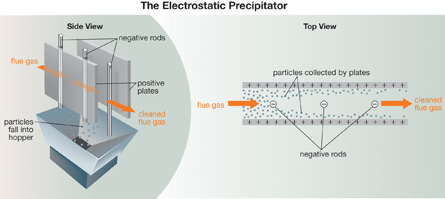
An electrostatic precipitator works using positively charged parallel plates, which sandwich negatively charged metal rods that hang between the plates. As the particles in the flue gas pass the negatively charged rods, the particles pick up negative ions and become negatively charged. These negatively charged particles are then attracted to the positive plates where they are collected. By the time the flue gas has passed through a long column of rods and plates, over 99% of the particulate matter has been removed. Periodically, the large positive plates are rapped with automated hammers, causing the particles to drop into the hoppers below the plates.
The pattern of the electric field lines within an electrostatic precipitator is a combination of the patterns formed by field lines between parallel plates with the patterns that surround negative sources.
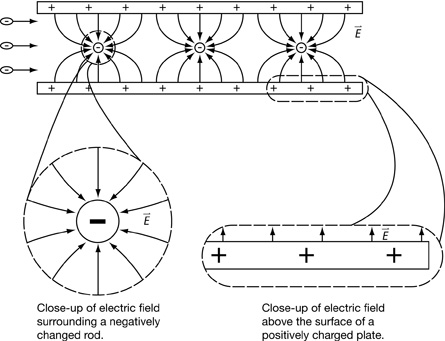
 Self-Check
SC 1. Classify the pattern of electric field lines close to the negatively charged rod as being either "uniform" or "radial.”
SC 2. Classify the pattern of electric field lines close to the positively charged plates as being either “uniform” or “radial.”
Self-Check Answers
SC 1. The electric field lines close to the negatively charged rod are radial since they are aligned along lines that converge at the centre of this circular pattern.
SC 2. The electric field lines close to the positively charged plates are uniform because the field lines are parallel and evenly spaced.
The Motion of Charged Particles in Radial Electric Fields
To develop an understanding of how an electrostatic precipitator works, you will first take a look at the motion of charged particles in radial electric fields.
 Read
Read
You can learn how the motion of charged particles can be analyzed in non-uniform electric fields by reading pages 570 and 571 of your textbook. Pay special attention to the way that the law of conservation of energy is used in “Example Problem 11.10.”
Self-Check
SC 3. Explain why the equations for accelerated motion could not be used for situations like the one described in “Example Problem 11.10.”
SC 4. Solve “Practice Problem” 2 on page 571 of your textbook.
Self-Check Answers
SC 3. The equations for accelerated motion describe motion when the acceleration is constant. In cases like “Example 11.10,” the electrostatic force acting on the particle is much stronger closer to a point source than it is further away. Applying Newton's second law of motion, the acceleration resulting from this force will also be much stronger closer to the source than at locations further away. Since the acceleration is not constant, the equations developed to describe uniformly accelerated motion cannot be used for situations like this.
SC 4.
Given
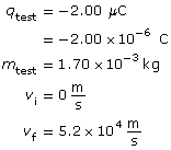
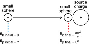
Required
The electric potential energy lost by the test charge.
Analysis and Solution
Initially the small test sphere is at rest so it has zero kinetic energy. However, at this location the system has electric potential energy relative to the source charge because it takes work to move the test charge away from the source charge. Since the system is conservative this loss of electric potential energy when the test charge moves toward the source is equal to the gain in kinetic energy.
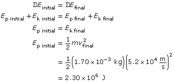
Paraphrase
The test charge lost 2.30×10³ J of electrical potential energy.
 Did You Know?

© Germany Feng/shutterstock
Many of the air-cleaning systems that you can buy for your home are actually small electrostatic precipitators. In these home units, a small fan forces air to pass by a long, negatively charged wire. Tiny particles in the air pick up negative ions and become negatively charged. As the stream of air passes by positively charged collection plates, the negative particles are attracted to the plates and are removed from the air. However, unlike the huge installations at power plants, there are no hammers to rap the collection plates and cause the collected particles to fall into a hopper. In these smaller home systems, the unit has to be unplugged before the plates can be removed and cleaned by hand.
1.43. Page 3
Module 3—Electrical Phenomena
The Motion of Charged Particles in Uniform Electric Fields

© Forgis/2463953/fotolia
The motion of an individual charged particle in a uniform electric field is not something that most people observe on a daily basis. However, the motion of a mass in a uniform gravitational field is something that almost everyone has experienced but may not know it.
Think back to the last time you were watching or playing sports when a ball was given a velocity and then allowed to move through Earth's gravitational field. If the batter in the photo connects her bat with the ball, what additional information would you need in order to predict the motion of the ball?
If spinning effects can be ignored, the motion of the ball depends upon the direction of the initial velocity of the ball once it leaves the bat. As you'll see in the next question, the path of the ball is a consequence of Newton's laws of motion.
 Self-Check
SC 5. In each of the following diagrams, the initial velocity of a softball is shown relative to the direction of the gravitational field. Make your own copy of each diagram, and add the following information:
- the direction of the force of gravity on the ball
- the path of the ball
- the concise explanation of the path that you drew
Ignore the effects of air resistance, and consider the force of gravity to be the only force acting on the ball.
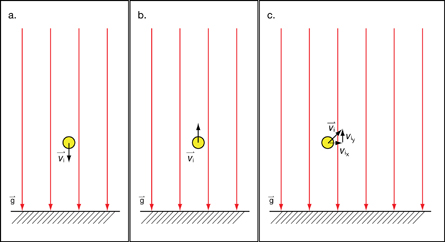
Self-Check Answers
SC 5.

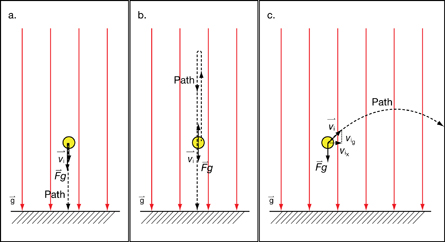
The force of gravity is the only force acting on the ball, so it is an unbalanced force.
According to Newton's second law of motion, the ball will accelerate in the direction of the unbalanced force—straight down toward Earth's centre. The downward acceleration is in the same direction as the initial velocity, so the ball speeds up as it travels on a path that takes it down—toward Earth’s centre. |
The force of gravity is the only force acting on the ball, so it is an unbalanced force.
According to Newton's second law of motion, the ball will accelerate in the direction of the unbalanced force—straight down toward Earth's centre. The downward acceleration is in the opposite direction as the initial velocity, so the ball initially slows down as it travels straight up, away from the centre of Earth. Eventually, the velocity of the ball reaches zero at its highest point. The ball continues to accelerate by speeding up as it travels straight down toward Earth’s centre. |
The force of gravity is the only force acting on the ball so it is an unbalanced force.
According to Newton's second law of motion, the ball will accelerate in the direction of the unbalanced force—vertically down, toward Earth's centre.
Ignoring the effects of air resistance, in the horizontal direction there are no unbalanced forces acting on the ball. Newton's first law of motion states that in the absence of an external, unbalanced force, an object will maintain its velocity. Therefore, the ball moves with uniform motion in the horizontal direction. In other words, the downward acceleration due to gravity is perpendicular to the horizontal component of the ball's initial velocity, so the ball’s horizontal motion is unaffected by this acceleration.
|
 Read
Read
You can learn how the motion of charged particles can be analyzed in uniform electric fields by reading pages 572 and 573 of your textbook. Note how kinetic and potential energy are assigned zero values in “Example Problem 11.11.”
Self-Check
SC 6. Solve “Practice Problem” 1 on page 573 of your textbook.
Self-Check Answers
SC 6.
Given
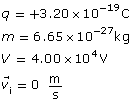
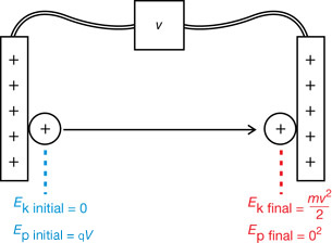
Required
The final speed of the alpha particle, the instant before hitting the negative plate.
Analysis and Solution
In terms of electric potential energy, if the electric potential energy at the negative plate is zero, then the electric potential energy of the system at the positive plate is E = qV. In terms of kinetic energy, the alpha particle is at rest at the positive plate so the kinetic energy at that location is zero. Just before striking the negative plate the kinetic energy of the alpha particle is ½mv−2final.
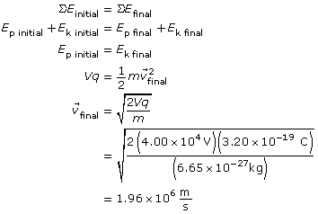
Paraphrase
The final speed of the alpha particle is 1.96×10⁶ m/s.
The same physics principles used to analyze the motion of a softball in the gravitational field of Earth can be used to analyze the motion of a charged particle moving in a uniform electric field. When a charge travels through a uniform electric field, the type of motion that results depends on the direction of the force acting on the particle relative to the direction of the particle's initial velocity. In the next lab activity you will have an opportunity to investigate this further.
1.44. Page 4
Module 3—Electrical Phenomena
 Lesson 6 Lab: Motion of Charges in Uniform Electric Fields
This lab consists of four parts. In Part A, you will examine the motion of a positively charged particle when it initially moves parallel to the electric field. In Part B you will examine the motion of a positively charged particle when it initially moves perpendicularly to the electric field. In Part C you will examine how a negatively charged particle will move when it starts parallel to the electric field. Finally, in Part D you will examine the motion of a negatively charged particle when it initially moves perpendicularly to the electric field.
Part A: Positive Particle Moves Parallel to the Electric Field
Purpose
In this part of the lab activity, you will use a computer simulation to collect data enabling you to answer the following questions:
- How does a positive particle move when the direction of its initial velocity is opposite to the direction of the electric field?
- How can this motion be explained using physics principles?
Procedure
Step 1: Open the Electric Field Potential simulation, and enter the following settings:
- Reset the simulation (
 ).
).
- Set the direction of the electric field to 0° W of S using the drop-down menu in the electric field display panel. Press the “enter” button on the keyboard to change the value in the textbox. Enter a value of 75 V/m for the magnitude of the electric field in the electric field display panel. Note that the electric field vector is shown as a large, green arrow. The small, green arrows indicate that the field has the same value at all locations on the screen.
- Set the direction of the initial velocity to 0° E of N using the drop-down menu in the velocity display panel. Enter a value of 150 m/s for the magnitude of the initial velocity in the velocity display panel. The velocity vector is shown as a magenta (purplish red) arrow.
- Set the particle's charge and mass to + 2.0 C and 3.0 kg, respectively.
- Drag the particle to a position low on the screen.
- Note that if you use “rewind” (
 ), you can return to these initial settings at any time during this lab activity. However, if you use “reset” (), you will have to re-enter all these initial settings.
If these settings have been applied, the screen should look like this:
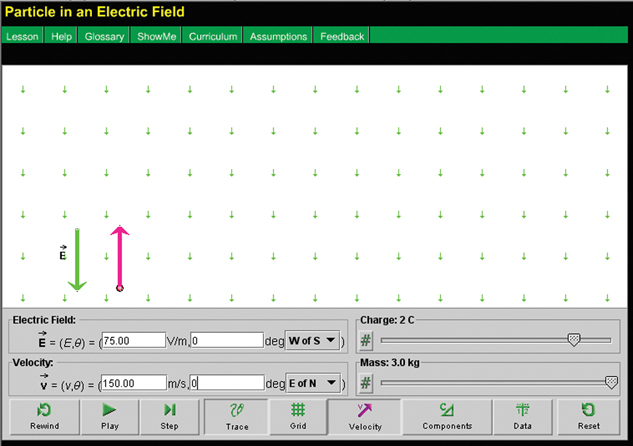
Step 2: Given these initial conditions, make a prediction as to how you think the particle will move if it is released. Press the “play” button (![]() ) to confirm your prediction.
) to confirm your prediction.
Step 3: Use “rewind” (![]() ) to return to the initial settings. Repeat the previous step, but use “pause” (
) to return to the initial settings. Repeat the previous step, but use “pause” (![]() ) to stop the motion at the instant the particle reaches its highest point. Use “data” (
) to stop the motion at the instant the particle reaches its highest point. Use “data” (![]() ) to display information about the elapsed time, Δt, the x and y components of the acceleration (x, y), and the x and y components of the displacement (dx, dy) from the start of the motion.
) to display information about the elapsed time, Δt, the x and y components of the acceleration (x, y), and the x and y components of the displacement (dx, dy) from the start of the motion.
Step 4: Collect the following data:
elapsed time Δt = ________ s
charge q = ____________ C
mass m = ___________ kg
Express the remaining values in terms of x and y components:
electric field ![]() = ___________V/m
= ___________V/m
acceleration (ax, ay) = ___________m/s2
initial velocity (vix, viy) = (0, 150) m/s
final velocity (vfx, vfy) = ____________m/s
maximum displacement (Δdx, Δdy) = __________m
Press the green button beside the ![]() once to see the final velocity in terms of x and y components.
once to see the final velocity in terms of x and y components.
final velocity (vfx, vfy) = ____________m/s
Note that the acceleration due to gravity is ignored in this simulation.
Analysis
 Self-Check
Note that the values will be close to, but not necessarily exactly the same as, the answers shown. This is because you might have a slightly different time, ±0.20 s. However, your results will match the simulation’s values.
SC 7. Use Newton's laws of motion to verify the x and y components of the acceleration.
SC 8. Use calculations to verify the x and y components of the maximum displacement.
SC 9. Describe and explain a situation involving gravitational fields that could produce a similar type of motion.
Self-Check Answers
SC 7.
Given
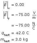
Required
The x and y components of the acceleration.
Analysis and Solution
- Newton’s second law states that an unbalanced force will cause a mass to accelerate in the direction of the force such that
 .
.
- In this case the electrostatic force supplies the unbalanced force according to
 . These equations can be combined to find the magnitude of the acceleration.

- Since the x and y components are independent of one another, the x and y components can be determined:
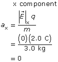
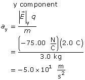
Paraphrase
In the x direction, the electric field is zero. Therefore, there is no force acting on the particle in the x direction and no acceleration. In the y direction, the electric field is ![]() , in the negative y direction. The resulting unbalanced force on the particle is also in the negative ydirection. These values are consistent with the values provided by the simulation, (0,−50.00)
, in the negative y direction. The resulting unbalanced force on the particle is also in the negative ydirection. These values are consistent with the values provided by the simulation, (0,−50.00) ![]() .
.
SC 8.
Given
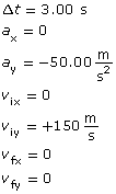
Required
The x and y components to the final displacement.
Analysis and Solution
In the x direction there is no motion since the velocity and acceleration values are all zero.
In the y direction the motion can be analyzed using a number of possible kinematics equations. One possible approach is shown here.
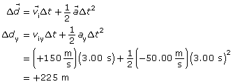
Paraphrase
The x and y components of the final displacement are (0, 225) m. These values are consistent with the values provided by the simulation (0, 225.1) m.
SC 9.
When a softball leaves a bat with an initial velocity directed straight up, the force of gravity acts to oppose the motion. Earth's gravitational field ensures that test bodies always experience a force of gravity directed downward—toward the centre of the planet.
According to Newton's second law, this downward force always causes an acceleration that is also directed downward—toward the centre of the planet. In terms of the motion of the ball, if it begins by moving straight up, it slows down, stops momentarily at the top of its path, and then speeds up as it returns to Earth.
 Module 3: Lesson 6 Assignment
Remember to submit the answers to LAB 1 and LAB 2 to your teacher as part of your Module 3: Lesson 6 Assignment.
LAB 1. Summarize what you have learned from this simulation by stating what will happen when
- a positive particle has an initial velocity opposite to the direction of the electric field.
- a positive particle has an initial velocity in the same direction as the electric field.
LAB 2. Use physics principles to explain the motion you described in LAB 1.
Part B: Positive Particle Moves Perpendicular to the Electric Field
Purpose
In this part of the lab activity you will use a computer simulation to collect data enabling you to answer the following questions:
- How does a positive particle move when the direction of its initial velocity is perpendicular to the direction of the electric field?
- How can this motion be explained using physics principles?
Procedure
Step 1: Open the Electric Field Potential, Uniform simulation, and enter the following settings:
- Reset the simulation ().
- Set the direction of the electric field to 0o W of S using the drop-down menu in the electric field display panel. Enter a value of 75 V/m for the magnitude of the electric field in the electric field display panel.
- Set the direction of the initial velocity to 0o S of E using the drop-down menu in the velocity display panel. Enter a value of 150 m/s for the magnitude of the initial velocity in the velocity display panel.
- Set the particle's charge and mass to +2.0 C and 3.0 kg, respectively.
- Drag the particle to a position on the left of the screen and centred vertically.
- Note that if you use “rewind” (), you can return to these initial settings at any time during this lab activity. However, if you use “reset” (), you will have to re-enter all these initial settings.
If these settings have been applied, the screen should look like this.
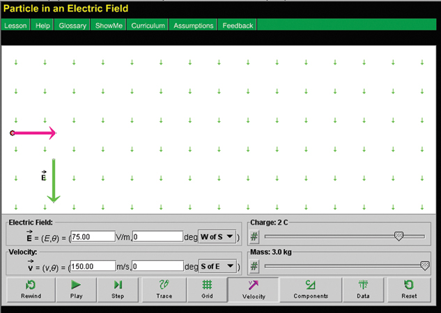
Step 2: Given these initial conditions, make a prediction as to how you think the particle will move if it is released. Press the “play” button (![]() ) to confirm your prediction. To see the path that the particle followed, use the “rewind” button (
) to confirm your prediction. To see the path that the particle followed, use the “rewind” button (![]() ). Then use the “trace” button (
). Then use the “trace” button (![]() ).
).
Step 3: Use “rewind” (![]() ) to return to the initial settings. Repeat the previous step, but use “pause” (
) to return to the initial settings. Repeat the previous step, but use “pause” (![]() ) to stop the motion at the instant the particle starts to leave the display. Use “data” (
) to stop the motion at the instant the particle starts to leave the display. Use “data” (![]() ) to display information describing the particle in this location.
) to display information describing the particle in this location.
Step 4: Collect the following data:
elapsed time
charge
mass
Δt = ________s
q = ____________C
m = ___________kg
Express the remaining values in terms of x and y components:
electric field
acceleration
initial velocity
final velocity
displacement
![]() = ___________V/m
= ___________V/m
(ax, ay) =___________m/s2
(vix, viy) = (150, 0) m/s
(vfx, vfy) = ____________m/s
(Δdx, Δdy) = __________m
Note that the acceleration due to gravity is ignored in this simulation.
Analysis
Self-Check
SC 10.
- Use calculations to verify the x component of the displacement.
- Use calculations to verify the y component of the displacement.
SC 11. Use calculations to verify the y component of the final velocity.
SC 12. Use calculations to verify the magnitude and the angle of the final velocity as displayed in the velocity display panel.
SC 13. Describe a situation involving gravitational fields that could produce a similar type of motion.
Self-Check Answers
Your answers may be slightly different due to different time values. However, your answers will match the simulation.
SC10.
a.
Given
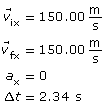
Required
The x component of the displacement.
Analysis and Solution
Since there is no x component of the electric field, there is no electrostatic force acting in the x direction. Therefore there is no acceleration in the x direction. In other words, the charge moves with uniform motion in the x direction.
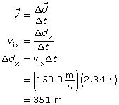
Paraphrase
The x-component of the displacement is calculated to be 351 m. This matches the value provided by the simulation.
SC10.
b.
Given
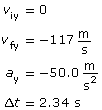
Required
The y component of the displacement.
Analysis and Solution
Since the y component of the electric field is in the negative y direction, the positive particle experiences an electrostatic force in the negative y direction. Since this electrostatic force is unbalance, the positive particle accelerates uniformly in the negative y direction.
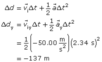
Note: in step 3, viy = 0 so the entire term is zero and is dropped for simplicity.
Paraphrase
The y component of the displacement is −137 m. This matches the value provided by the simulation.
SC11.
Given
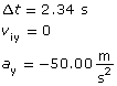
Required
The y component of the final velocity
Analysis and Solution
Since the y component of the electric field is in the negative y direction, the particle experiences an electrostatic force in the negative y direction. Since this electrostatic force is unbalanced, the positive particle accelerates uniformly in the negative y direction.
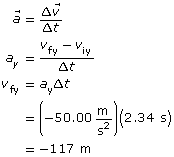
Note: in step 3, viy = 0 so it is dropped for simplicity.
Paraphrase
The y component of the final velocity of the particle is calculated to be −117 m/s. This matches the value provided by the simulation.
SC12.
Given
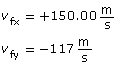
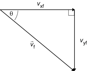
Required
The magnitude and the direction of the final velocity.
Analysis and Solution
The magnitude of the velocity can be found using the Pythagorean theorem. The direction can be found using trigonometry.
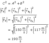
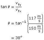
Paraphrase
The final velocity is calculated to be 190 m/s [38° S of E]. This matches the value provided by the simulation.
SC 13. A similar type of motion could be produced if an object were launched horizontally from the edge of a cliff. The initial velocity would be at a right angle to the gravitational field, so if the effects of air resistance could be ignored, the object would maintain its velocity in the horizontal direction while accelerating in the vertical direction. The resulting path would be the characteristic parabola of projectile motion.
Module 3: Lesson 6 Assignment
Remember to submit the answers to LAB 3 and LAB 4 to your teacher as part of your Module 3: Lesson 6 Assignment.
LAB 3. Describe the motion of a positive particle when the direction of its initial velocity is perpendicular to the direction of the electric field.
LAB 4. Use physics principles to explain the motion you described in LAB 3.
Part C: Negative Particle Moves Perpendicular to the Electric Field
Purpose
In this part of the lab activity you will use a computer simulation to collect data enabling you to answer the following question:
- How does a negative particle move when the direction of its initial velocity is perpendicular to the direction of the electric field?
- How can this motion be explained using physics principles?
Procedure
Step 1: If you still have the simulation open from Part B of this lab activity, continue with the next step. Otherwise, re-open the Electric Field Potential, Uniform simulation, and enter the settings described in Step 1 of Part B.
Step 2: To return the particle to its initial position, press “rewind” (![]() ).
).
Step 3: Make the following adjustments to the initial settings:
- Change the charge of the particle to –2.0 C.
- Set the direction of the initial velocity to 0o N of E using the drop-down menu in the velocity display panel. Enter a value of 150 m/s for the magnitude of the initial velocity in the velocity display panel.
If these settings have been properly applied, the screen should look like this:
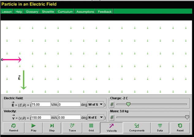
Step 4: Given these initial conditions, predict how the particle will move if it is released. Press the “play” button (![]() ) to confirm your prediction.
) to confirm your prediction.
Step 5: Use “rewind” (![]() ) to return to the initial settings. Repeat the previous step, but use “pause” (
) to return to the initial settings. Repeat the previous step, but use “pause” (![]() ) to stop the motion at the instant the particle starts to leave the display. Use “data” (
) to stop the motion at the instant the particle starts to leave the display. Use “data” (![]() ) to display information describing the particle at this location.
) to display information describing the particle at this location.
Step 6: Collect the following data:
elapsed time
charge
mass
Δt = ________s
q = ____________C
m = ___________kg
Express the remaining values in terms of x and y components:
electric field
acceleration
initial velocity
final velocity
displacement
![]() = ____________V/m
= ____________V/m
(ax, ay) =_____________m/s2
(vix, viy) = (150, 0) m/s
(Δdx, Δdy) = __________m
(vfx, vfy) = ____________m/s
Note that the acceleration due to gravity is ignored in this simulation.
Analysis
Self-Check
SC 14. a. Use calculations to verify the x component of the displacement.
- Use calculations to verify the y component of the displacement.
SC 15. Use calculations to verify the y components of the final velocity.
SC 16. Use calculations to verify the magnitude and direction of the final velocity as displayed in the velocity display panel.
SC 17. In this part of the lab, a particle that had an initial velocity perpendicular to a field moved through a parabolic trajectory so that it accelerated in a direction opposite to the external field. Explain why this situation could never happen in a gravitational field.
Self-Check Answers
SC 14.
a.
Given
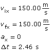
Required
The x component of the displacement.
Analysis and Solution
Since there is no x component of the electric field, there is no electrostatic force acting in the x direction. In other words the charge moves with uniform motion in the x direction.
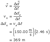
Paraphrase
The x component of the displacement is calculated as 369 m, which matches the value provided by the simulation.
b.
Given
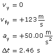
Required
The y component of the displacement.
Analysis and Solution
Since the y component of the electric field is in the negative y direction, the particle experiences an electrostatic force in the positive y direction. This is because the charge is negative and experiences a force opposite to the direction of the electric field. Since the electrostatic force is unbalanced, the negative particle accelerates in the positive y direction.
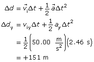
Paraphrase
The y component of the displacement is calculated as +151 m, which matches the value provided by the simulation.
SC 15.
Given
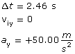
Required
The y component of the final velocity
Analysis and Solution
The y component of the electric field is in the negative y direction. However because the particle is negative, it experiences a force in the positive y direction. (See SC 14.b. for explanation) The electrostatic force in the positive y direction is unbalanced, so the negative particle accelerates in the positive y direction.
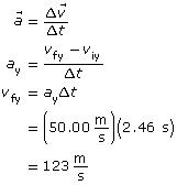
Paraphrase
The y component of the final velocity is calculated to be 123 m/s. This matches the value provided by the simulation.
SC 16.
Given
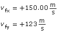
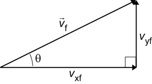
Required
The magnitude and direction of the final velocity.
Analysis and Solution
The magnitude of the velocity can be found by using the Pythagorean theorem. The direction can be found by using trigonometry.
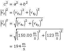

Paraphrase
The final velocity is calculated to be 194 m/s [39o N of E], which matches the value provided by the simulation.
SC 17. There are two types of test bodies that can be accelerated in electric fields: positively charged test bodies and negatively charged test bodies. Positively charged particles accelerate in the same direction as the electric field, and negatively charged particles accelerate opposite to the direction of the field.
However, in gravitational fields there is only one kind of test body: an object with mass. Objects with mass always accelerate in the same direction as the gravitational field. So it is impossible for a test mass to be injected at right angles to a gravitational field and then accelerate in a direction that is opposite to that of the field.
Module 3: Lesson 6 Assignment
Remember to submit the answers to LAB 5 and LAB 6 to your teacher as part of your Module 3: Lesson 6 Assignment.
LAB 5. Describe the motion of a negatively charged particle when the direction of its initial velocity is perpendicular to the direction of the electric field.
LAB 6. Use physics principles to explain the motion you described in LAB 5.
Part D: Producing an Un-deflected Path Through an Electric Field
Purpose
In this part of the lab activity you will use a computer simulation to collect data enabling you to answer the following question:
- If a particle is given an initial velocity perpendicular to an electric field, under what circumstance could this particle move un-deflected with uniform motion through the electric field? Assume the electric field is the only field present.
Procedure
Step 1: If you still have the simulation open from this lab activity, continue with the next step. Otherwise, re-open the Electric Field Potential, Uniform simulation, and enter the settings described in Step 1 of Part B.
Step 2: To return the particle to its initial position, press “rewind” (![]() ).
).
Step 3: Without changing the settings for the electric field or the velocity, what adjustment could you make so that the particle moves with only uniform motion when you release the particle? Make the necessary adjustment and press “play” (![]() ) to confirm your prediction.
) to confirm your prediction.
Step 4: Use “rewind” (![]() ) to return to the initial settings. Repeat the previous step, but use “pause” (
) to return to the initial settings. Repeat the previous step, but use “pause” (![]() ) to stop the motion at the instant the particle starts to leave the display. Use “data” (
) to stop the motion at the instant the particle starts to leave the display. Use “data” (![]() ) to display information describing the particle in this location.
) to display information describing the particle in this location.
Self-Check
SC 18. Identify the values on the data chart that confirm that the particle is only moving with uniform motion.
Self-Check Answer
SC 18. One set of values that confirm that the particle is only moving with uniform motion are the values for acceleration. Both the x and y components of the acceleration are zero.
Module 3: Lesson 6 Assignment
Remember to submit the answer to LAB 7 to your teacher as part of your Module 3: Lesson 6 Assignment.
LAB 7. Explain the circumstances that enable an article to move un-deflected with uniform motion through an electric field if it is given an initial velocity perpendicular to the electric field. Assume the electric field is the only field present.
1.45. Page 5
Module 3—Electrical Phenomena

© Nagy Melinda/shutterstock
Pulling it All Together: Charges, Fields, and Projectile Motion
As a soccer ball arcs through the air from one end of the field to the other, its path follows the characteristic pattern of a projectile, a parabolic trajectory. In the previous lab activity you used a computer simulation to discover that a charged particle can also move through a parabolic trajectory. The analysis of the data from the simulation revealed that the same equations that you used to analyze projectile motion in previous courses can be applied to a charged particle moving through a uniform electric field.
Now it’s time to apply these analytical skills to problem solving. In the next activity you will have an opportunity to apply what you learned to a variety of new situations.
Sketching the Paths of Charged Particles in Uniform Electric Fields
In the previous lab activity you developed some general statements that described how charged particles would move in specific circumstances. In this activity you will have a chance to apply those statements as you predict the motion of individual particles moving through electric fields.
Purpose
In this activity you will sketch the paths of charged particles in a number of different circumstances.
Procedure
Answer the following Assignment question.
 Module 3: Lesson 6 Assignment
Remember to submit the answer to A 1 to your teacher as part of your Module 3: Lesson 6 Assignment.
A 1. In your Module 3: Lesson 6 Assignment, diagrams show the initial position and the velocity vector of a charged particle within a uniform electric field. For each diagram, follow each of these steps:
- Sketch a free-body diagram showing the net force that acts on the particle.
- Sketch the path of the particle.
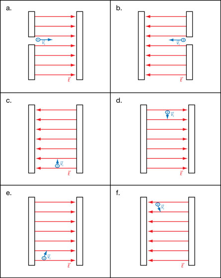
 Self-Check
SC 19. The following diagram shows an electron entering the region between two oppositely charged plates. The plates are 55.0-mm long and are separated by 19.5 mm. A potential difference of 0.133 V across the plates generates a uniform electric field in the region between the plates. The electron is given an initial velocity of 8.50 × 10⁵ m/s in the positive ydirection. Use this information to determine the final velocity of the electron when it leaves the region between the plates.
Be sure to begin your solution with a free-body diagram and an analysis of the physics principles that will support your solution.
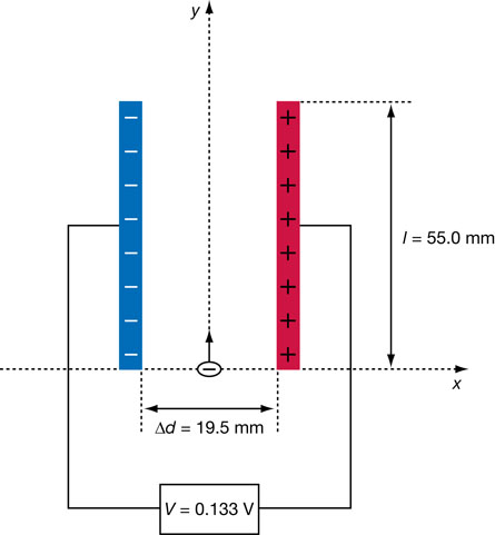
Self Check Answer
SC 19.
Given
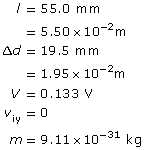
Required
The magnitude and direction of the final velocity of the electron.
Analysis and Solution
Step 1: Free-body diagram and statement of the physics principles.
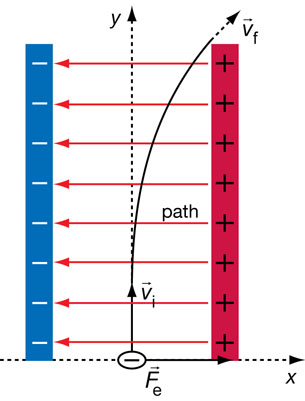
- The electric field between the plates points in the negative x direction.
- Since the particle is negatively charged, the electrostatic force on the particle will act in the positive x direction.
- The electrostatic force will cause the particle to accelerate in the positive x direction. This is in accordance with Newton’s second law of motion.
- Since there is no unbalanced force acting in the y direction, the particle will move with uniform motion in the positive y direction. This is in accordance with Newton’s first law of motion.
- The path of the particle is a parabolic trajectory. This is a consequence of uniform motion in the positive y direction combined with accelerated motion in the positive x direction.
Step 2: Determine the magnitude of the electrostatic force.
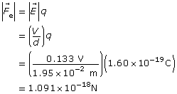
Step 3: Determine the magnitude of the acceleration in the positive x direction
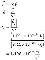
Step 4: Determine the time for the particle to travel to the end of the region between the plates. Use the fact that the motion in the y direction is uniform.
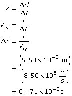
Step 5: Determine the final velocity in the x direction.
Step 6: Use the x and y components to find the final velocity. Since the motion in the y direction is uniform vfy = +8.50×10⁵ m/s.
Paraphrase
The final velocity of the electron when it leaves the region between the plates is 8.54×10⁵ m/s [85°].
Module 3: Lesson 6 Assignment
Remember to submit the answer to A 2 to your teacher as part of your Module 3: Lesson 6 Assignment.
A 2. The following diagram shows a proton entering the region between two oppositely charged plates. The plates are 45.0 mm long and are separated by 17.5 mm. A potential difference of 0.208 V generates an electric field between the plates. The proton is given an initial velocity of 1.35 × 10⁴ m/s in the positive x direction. Use this information to determine the y component of the displacement of the proton when it leaves the region between the plates. (Note: This displacement is how far the proton has moved above or below the x-axis the instant it leaves the region between the plates.)
Be sure to begin your solution with a free-body diagram and an analysis of the physics principles that apply.
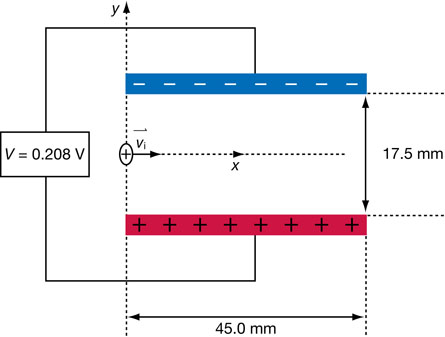
1.46. Page 6
Module 3—Electrical Phenomena
 Reflect and Connect

© Mark Winfrey/shutterstock
The engineers who design electrostatic precipitators for coal-fired generating stations have to balance the need to significantly reduce the particulate matter that enters the air with the need to run the units efficiently. Since the electric fields within the units are sustained by high-voltage sources, it makes sense to create a design that effectively removes the particulate matter using the minimum amount of electrical energy. Keep these ideas in mind as you answer the following questions.
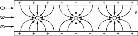
 Try This
TR 1. The electric field between the negatively charged rods and the positively charged plates of an electrostatic precipitator has to be strong enough to generate negatively charged ions that can be picked up by the particles in the flue gas. If the field is not strong enough, then the some of the particles might remain uncharged while in the electrostatic precipitator. Explain the outcome for a microscopic bit of coal dust within the electrostatic precipitator if it remains uncharged.
TR 2. A key consideration for the design engineers is the speed of the particles within the flue gas. The faster the charged particles move, the more difficult it is to deflect them toward the collector plates.
- Produce a simple sketch to illustrate why it is more difficult to deflect a fast-moving charged particle than a slow-moving charged particle in a given electric field. Assume that each particle has the same mass and charge.
- Identify two reasons why increasing the strength of the electric field within the electrostatic precipitator makes it easier to deflect the particles in the flue gas.
- Explain why it is easier to deflect particles within the flue gas to the collector plates if the collector plates are kept close together and made as long as possible.
- Post your solutions to the discussion area. Read some of the other solutions from other students. Choose which of the solutions from the postings is best and identify why you think so.
 Module 3: Lesson 6 Assignment
Remember to submit the answers to your assignment questions to your teacher.
1.47. Page 7
Module 3—Electrical Phenomena
 Lesson Summary
At the beginning of this lesson, you were asked the following essential questions:
- How do charged particles move in a uniform electric field? How is this motion similar to a mass moving in a gravitational field?
- Is it possible to predict the velocity, acceleration, and displacement of charged particles moving in electric fields?
Charged particles in uniform electric fields move according to Newton’s laws of motion. This makes the motion of a charged particle very similar to the motion of a mass in a gravitational field. In both cases, the test body accelerates in the direction of an unbalanced force as described by Newton’s second law. If there is no unbalanced force, then the test body maintains its velocity as described by Newton’s first law. If one component of the velocity of a test body is maintaining a constant velocity, while another component is accelerating, then the test body will move through a parabolic trajectory or projectile motion.
The equations used to analyze projectile motion in previous courses can be applied to the motion of a charged particle in a uniform electric field.
For example, the equation Δd =½aΔt2 can be applied not just to projectile motion in a gravitational field, but also to the motion of a charged particle in a uniform electric field. To apply the formula to the motion of a charged particle, you simply take the variable a to refer to the acceleration due to the force of the uniform electric field.
The formula for projectile motion can be used to calculate the velocity, displacement, and acceleration of the motion of charged particles. The engineers who design electrostatic precipitators use the formulas of projectile motion to ensure that these devices work to effectively remove over 99% of the particulate matter from the flue gases produced at coal-fired generating stations.
1.48. Module Summary/Assessment
Module 3—Electrical Phenomena
 Module Summary
In Lesson 1 you looked at key concepts that are essential to understanding electrostatics, including the attraction and repulsion of charges, the law of conservation of charge, and the three methods of transferring charge: by friction, by conduction, and by induction.
In Lesson 2 you worked with Coulomb’s law:
![]()
This law says, if the charges are held constant and the distance of separation increases by some factor, then the effect on the resulting electrostatic force can be predicted. For example, if the distance increases by a factor of four, then the electrostatic force would be 1/16th its original value.
In Lesson 3 you learned more about the enormous amounts of charge that a lightning strike can deliver from a cloud to Earth. You also saw that Coulomb’s law can be used to calculate the net force on one point charge due to other point charges. You looked at solutions to these sorts of problems, which required you to consider the vector nature of electrostatic forces.
In Lesson 4 you learned that an electric field is the property of space surrounding a source charge that enables the source charge to exert forces on other charges that enter this region. One way to describe electric fields is to use equations:
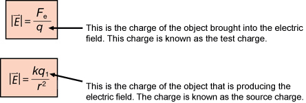
The direction of an electric field is determined by the direction of the electrostatic force experienced by a small positive test charge. This can be used to describe electric fields in terms of patterns of electric field lines around source charges.
In Lesson 5 you saw that both electric potential energy and gravitational potential energy result when work is done to move an object in a field. In both cases, work is done by applying an external force on the object that is opposite to the force that the field would exert on the object. Gravitational potential energy can be increased when a mass is moved up, away from Earth’s surface, and parallel to the gravitational field. Electric potential energy can be gained by moving a positive charge toward a positive source, or by moving a negative charge away from a positive source. In both cases the distance moved is parallel to the electric field.
While potential energy is measured in joules, electric potential is measured in volts. A volt is a joule per coulomb. Many people prefer to use the term voltage for electric potential because it reminds them how this quantity is measured.
In Lesson 6 you learned that charged particles in uniform electric fields move according to Newton’s laws of motion. This makes the motion of a charged particle very similar to the motion of a mass in a gravitational field. In both cases the test body accelerates in the direction of an unbalanced force. If there is no unbalanced force, then the test body maintains its velocity. The equations used to analyze projectile motion in previous courses can be applied to the motion of a charged particle in a uniform electric field.
For example, the equation Δd =½aΔt2 can be applied not just to projectile motion in a gravitational field, but also to the motion of a charged particle in a uniform electric field. The formula for projectile motion can be used to calculate the velocity, displacement, and acceleration of the motion of charged particles.
 Module Assessment
As your module assessment do the following two questions. The first is a graphing question, and the second is a holistic question.
Use the following information to answer this graphing question.
A student performed an experiment that verified Coulomb’s Law of Electrostatics by measuring the repulsion between two charged spheres, A and B, as a function of the separation of the spheres. The spheres were identical in size and mass. The measurements are shown in the table of values and plotted on the graph below.
Separation (m)
0.10
0.13
0.20
0.40
0.60
Force (N)
0.790
0.480
0.200
0.050
0.022
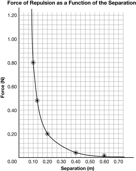
- Show that the results verify Coulomb’s law by manipulating the data and providing a new table of values that, when plotted, will produce a straight-line graph.
- Plot the new data with the responding variable on the vertical axis.
- Calculate the slope of your graph.
- Using the slope value or another suitable averaging technique, determine the charge on sphere B if the charge on sphere A is 3.08 × 10⁻⁷ C
- Determine the magnitude of the force between spheres A and B when they are at a distance of 2.00 m apart. Use the hypothetical value of 4.00 × 10⁻⁶ C for the charge on sphere B if you were unable to determine the actual value.
Graphing
(5 marks)
Scoring Guides for Graphing Skill-Based Questions––Mathematical Treatment
Score |
Description |
5 |
Note: one minor error may be present.* |
4 |
or
|
3 |
|
2 |
|
1 |
|
0 |
|
*Minor errors include:
- Misreading a data value while interpolating or extrapolating up to one-half grid off.
- Stating the final answer with incorrect (but not disrespectful) units.
- Stating the final answer with incorrect (but not disrespectful) significant digits.
- Missing one of several different formulas.
**Implicit treatment means:
- Substituting appropriate values into a formula from the data sheets without stating the formula.
- Starting with memorized, derived formulas not given on the equations sheet.
- Substituting the value from one calculation into a second formula without communicating that the physics quantity in the two formulas is the same.
***Major errors include:
- Using off-line points (most often, this is calculating the slope using data points that are not on a linear line of best fit).
- Using a single data point ratio as the slope.
- Missing powers of 10 in interpolating or extrapolating.
Use the following information to answer this holistic question.
A relatively new type of painting procedure is called powder coating. This new process is very different than traditional liquid paints. Liquid paints dissolve the coloured paint particles in a solvent. When the solvent evaporates, the paint particles are left behind and form the paint coating. Powder coating is much more like a photocopier or laser printer. The dry powdered plastic paint particles are given an electrostatic charge as they are blown out of the paint gun. The particles are then deposited on the charged or grounded target. Once the target is coated, it is baked which melts the powder to create a very even durable paint covering when cooled.
There are two types of powder painting paint guns: the corona and the tribo.
A corona paint gun works by using a negatively charged electrode with a potential difference of 30 kV to 100 kV at the nozzle where the powder particles come out. The target is given a positive charge. Corona paint guns are often used because they can paint large areas quickly with little wasted paint and good “wrap around’ effect. The one large disadvantage is that the corona guns experience faraday cage effect.
A tribo gun often uses multiple smaller pipes with a Teflon liner. As the nylon paint powder goes through the Teflon lined pipes it picks up a positive charge before leaving the gun. The target is grounded. Tribo guns require specific tribo paint powders made from nylon. They are not as fast as corona guns but they don’t suffer from faraday cage effect.
Faraday cage effect occurs when powder paint particles will not enter small openings in a surface due to the electrostatic forces. Corona guns suffer this effect whereas tribo guns do not.

- Compare and contrast how each gun charges the paint powder.
- Why are corona guns affected by the Faraday cage effect whereas tribo guns are not?
- Explain why electrostatic spraying of powdered paint is far more efficient in terms of the amount of paint that attaches to the target than sprayed liquid paint.
Holistic Scoring Guide
Major Concepts: Conservation of charge, electric fields, electric forces |
|
Score |
Description |
5 |
The nature of a response that will receive a score of 5 has the following characteristics:
Note: the response may contain minor errors or have minor omissions. |
4 |
The nature of a response that will receive a score of 4 has the following characteristics:
Note: the response is mostly complete and mostly correct, although it may contain errors or have omissions, and contains some application of physics principles. |
3 |
The nature of a response that will receive a score of 3 has the following characteristics:
|
2 |
The nature of a response that will receive a score of 2 has the following characteristic:
|
1 |
The nature of a response that will receive a score of 1 has the following characteristic:
|
0 |
The student provides a solution that is invalid for the question. |
* Explicit means the response is clearly stated; the marker does not have to interpret.
** Implicit (implied) means the response is not clearly stated; the marker must interpret.
For example:
Explicit: An electron has a negative charge while a proton has a positive charge.
The answer is clear with no possible misinterpretation.
Implicit: An electron has a negative charge while a proton does not.
The answer is not clear because the marker does not know if a proton is neutral or positively charged. There is more than one possible way to interpret the answer.
Your answers must clearly communicate your understanding of the physics principles you used to solve these questions. You may communicate this understanding mathematically, graphically, and/or with written statements.
1.49. Module Glossary
Module 3—Electrical Phenomena
Module Glossary
Coulomb’s law: the magnitude of the electrostatic force between two charged objects is directly proportional to the product of the two charges on the objects and inversely proportional to the square of the distance of separation between their centres
electric field: a property of the space around a source charge that enables the source charge to exert forces on test charges in the region
electric potential difference: the change in electric potential experienced by a charge moving from one point to another in an electric field
It is sometimes called potential difference.
field: a region of influence surrounding an object through which a force operates
grounding: the process of transferring charge to and from Earth
torsion balance: an instrument designed to measure small forces by the twisting of a thin wire
voltage: the value, in volts, of the change in electric potential energy stored per unit of charge
It is also called electric potential.