Module 3
1. Module 3
1.26. Page 4
Module 3—Electrical Phenomena
Lightning and Earth’s Electric Field
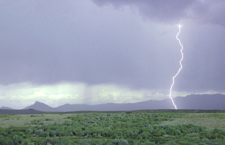
© Brandon Poleski/shutterstock
Each day, there are about 45 000 thunderstorms worldwide. Earth has acquired a net charge from the lightning strikes and therefore surrounds itself with a weak electric field.
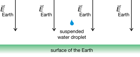
Investigations of this phenomenon indicate that, near the surface, Earth’s electric field is typically 150 N/C directed straight down toward the centre of the planet. When the field is constant, the field lines are evenly spaced, as indicated in this diagram.
Under the right circumstances, a tiny, charged droplet of water could be suspended in Earth’s electric field. In this circumstance, the electrostatic effects counteract the effects of gravity, so the drop would no longer be accelerating toward Earth’s surface.
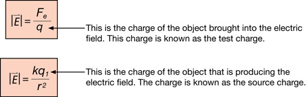
You have the tools to analyze this situation, but you have to be careful to use the equations for electric field correctly. It is important to remember that one equation deals with the charge on a test body, while the other equation deals with the charge on the source of the electric field.
 Self-Check
SC 8. Use the diagram of Earth’s electric field to determine the sign of the net charge on Earth.
Self-Check Answer
SC 8. The diagram of Earth’s electric field shows the field lines directed toward the surface of the planet. This indicates that Earth has a net negative charge. The reason is that electric field lines always point toward a negatively charged source. This is because electric field lines always show the way a positive test charge is forced. So if a positive test charge is attracted toward Earth, the planet must have a net negative charge.
The Vector Addition of Electric Fields
© Image courtsey of Shutterstock.com
St. Elmo’s fire is very difficult to photograph; a camera does not detect the faint blue glow very well, and St. Elmo’s fire occurs in circumstances that make photography difficult. A photographer would have to be close to the top of a ship’s mast in a thunderstorm or just behind the trailing edge of an aircraft wing in flight!
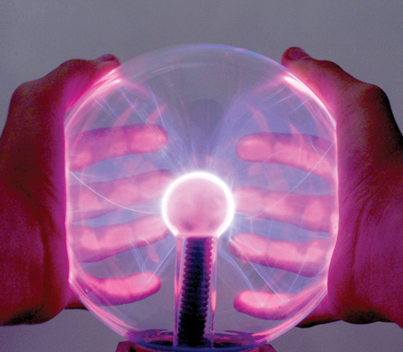
An alternative approach is to photograph a phenomenon that is similar to St. Elmo’s fire. Strictly speaking, the blue streamers of light visible in the photo of this plasma lamp are not St. Elmo’s fire. Nevertheless, the ribbons of light in a plasma lamp do have many things in common with St. Elmo’s fire:
- The effects are due to the presence of strong electric fields.
- The electric fields strip some electrons from gaseous molecules producing a hot, ionized gas called plasma.
- Light is emitted when electrons drop to lower energy levels within atoms.
- The colour of the emitted light depends upon the particular atoms affected.
© Sarah Harland/shutterstock
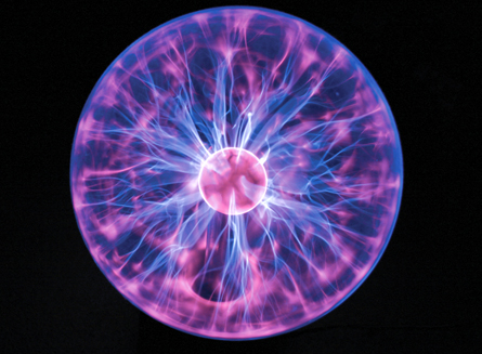
Since the atmosphere is comprised mostly of nitrogen, the light emitted from St. Elmo’s fire is blue, which is the characteristic colour emitted when nitrogen atoms are ionized. The manufacturers of plasma lamps deliberately introduce other gases to produce dramatic effects.
© ErickN/shutterstock
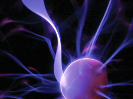
The streamers of light in this close-up photograph of a plasma lamp are particularly beautiful, not only because the colour is so striking but also because of the graceful, twisting shapes. These shapes are caused by charged particles within the streamers that are under the influence of more than one electric field. St. Elmo’s fire also involves overlapping electric fields that simultaneously influence many charges.
 Read
Read
To see what happens when electric fields with only x components overlap, read from the bottom of page 549 to the end of “Example 11.3” on page 550 of your textbook. As you read through this example, first identify the key steps and then focus on the details in each step.
Self-Check
SC 9. Refer to the previous photos of the plasma lamp. Simplify the situation and suppose that the charged particles within the streamer were only under the influence of the electric field of the negatively charged central orb. If this simplification were true, what shape would the streamers have?
SC 10. Try “Practice Problems” 1 and 2 on page 550 of your textbook. For question 2 remember the charge on a proton and electron is equal to the elementary charge on your datasheet.
Self-Check Answer
SC 9. If the negatively charged central orb was the only source of electric fields, then the electric field lines would be straight—pointing to the centre of the source. Positive ions would be forced to move along these lines and would be attracted to the source, while electrons would be forced to move along these lines to the outside. In this simplified approach, it follows that the streamers would form straight lines, radiating out from the centre.
SC 10.
Page 550 Practice Problem 1
Given
Required
The electric field strength at point P.
Analysis and solution

Paraphrase
The electric field at point P is 3.67×10⁷ N/C [left].
Page 540 Practice Problem 2
Given
Required
The electric field halfway between the electron and proton.
Analysis and solution
Since the magnitude of the charge of the electron and proton is the same, and the distance from each particle to the point is the same, the magnitude of the electric field due to the electron and the proton will be the same.
Since the charge on the electron is negative, the electric field caused by the electron will be toward the electron. Since the charge on the proton is positive, the electric field caused by the proton will also be toward the electron.
Paraphrase
The resultant electric field is 4.11×10¹² N/C [toward the electron].
Read
To see what happens when electric fields are described with both x and y components, read “Example 11.4” on pages 551 and 552 of your textbook. As you read through this example, first identify the key steps and then focus on the details in each step.
Self-Check
SC 11. Do “Practice Problem” 1 on page 551 of your textbook.
Self-Check Answer
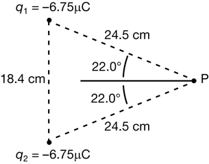
SC 11.
Given
q1 = +2.00 C
q2 = +2.00 C
r1 = 0.100 m
r2 = 0.100 m
Required
The electric field at point P.
Analysis and Solution
Since q1 and r1 are the same magnitude as q2 and r2, the magnitude of the electric fields will be the same; however, the directions will be different.
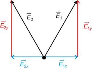
Note that the x components of electric field one and electric field two are in opposite directions but have equal magnitude. Therefore the two cancel each other out.
The resultant electric field at point P is the sum of the y components.
Paraphrase
The electric field at point P is 3.43×10¹² N/C [90°].
 Module 3: Lesson 4 Assignment
Remember to submit the answer to A 3 and A 4 to your teacher as part of your Module 3: Lesson 4 Assignment.
A 3. Point P is collinear with a +2.80 μC and a −8.50 μC as shown in the following diagram. Point P is 10 cm to the left of the positive charge and 20 cm to the left of the negative charge. What is the electric field at point P?
![]()
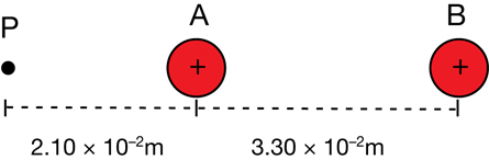
A 4. The following diagram shows two charged spheres arranged to the left of a point in space labelled P. Use the information on the diagram to calculate the magnitude and direction of the net electric field at point P.