Module 4
1. Module 4
1.18. Page 3
Module 4—Magnetic and Electric Fields in Nature and Technology
 Try This
Before you answer TR 2, watch Quicklab 12-4 to see a demonstration of a current-carrying conductor in a uniform magnetic field.
TR 2. Answer “QuickLab” questions 1 to 3 on page 606 of the textbook.
Example Problem 2.
The answer to “QuickLab” question 4 on page 606 of the textbook is provided below.
Apparatus
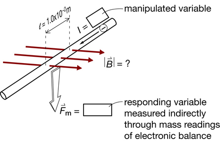
The following schematic gives an overview of the key principles that the experiment will use.
Materials Required
-
magnets to provide the magnetic field
-
some way to measure the force—an electronic balance perhaps
-
a variable source of current
-
a straight conductor and some way to insulate it
-
connecting wires from the straight conductor to the current source
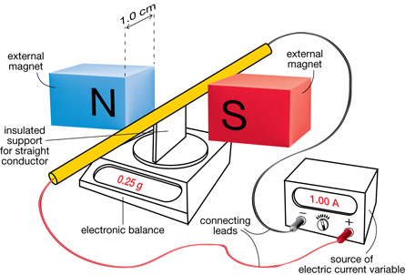
The following diagram shows one possible set up.
Procedure
-
Begin by conducting a safety audit. Exercise caution, given that current values will range from 1.0 A to 5.0 A.
-
Decide which way to connect the leads to the straight conductor: one way causes the magnetic force to be directed straight down (resulting in an increased reading on the balance, the desired scenario) and the other way causes the magnetic force to be directed straight up (resulting in a decreased reading on the balance).
-
"Zero" the balance when electric current reads zero amperes.
-
Begin the data collection. A table like the one following could be used to record the needed information:
Electric Current |
Mass |
Corresponding Force |
0 |
0 |
0 |
1.0 |
|
|
2.0 |
|
|
3.0 |
|
|
4.0 |
|
|
5.0 |
|
|
- Adjust the knob on the source of electric current to increase the value of the electric current flowing through the wire. Increases such as those suggested in the data table could be used for ease of analysis. The corresponding value on the electronic balance would be recorded in each case.
- Begin the data analysis by calculating the corresponding force for each current level (Fm = m × 9.81 m/s2). The following chart shows one set of measurements and the results of the calculations.
Electric Current |
Mass |
Corresponding Force |
0 |
0 |
0 |
1.0 |
0.25 |
2.5 × 10⁻³ |
2.0 |
0.51 |
5.0 × 10⁻³ |
3.0 |
0.74 |
7.3 × 10⁻³ |
4.0 |
1.03 |
10.1 × 10⁻³ |
5.0 |
1.27 |
12.5 × 10⁻³ |
-
Graph the data.
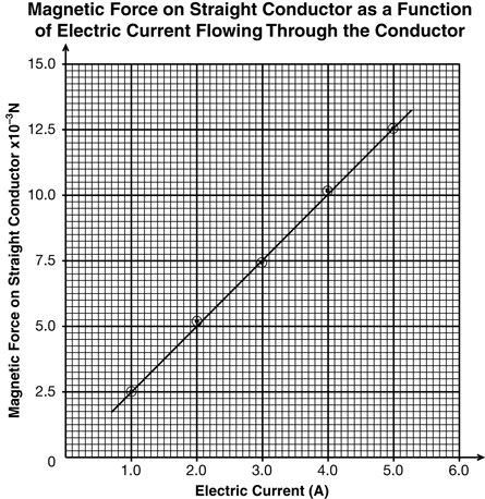
- Find the slope and use its value to calculate the strength of the magnetic field in the region between the two magnets.
From the graph
From the formula

Conclusion
The strength of the magnetic field is 0.25 T.