Module 4
1. Module 4
1.20. Page 5
Module 4—Magnetic and Electric Fields in Nature and Technology
Module 4: Lesson 3 Lab—The Generator Effect
In this lab you will investigate how a changing magnetic field can induce an electrical current in a conductor. In order for the generator effect to occur, there must be relative motion between an external magnetic field, such as that produced by a bar magnet, and a conducting wire. By forming the conducting wire into a loop, the generator effect can be amplified and observed using a galvanometer (to measure the current) or a voltage meter (to measure the charge separation as a result of the current).
Problem
What factors increase the current produced in a generator?
Materials
“Faraday’s Electromagnetic Lab” simulation
Procedure
- Open “Faraday’s Electromagnetic Lab” simulation. Select the “Pickup Coil” tab at the top of the simulation window and select the voltage meter instead of the light bulb as the indicator.
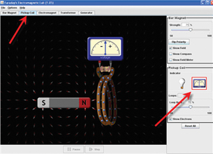
© PhET Interactive Simulations, University of Colorado. Some rights reserved.
- Move the bar magnet back and forth through the loop of wire, and observe the voltage meter. Answer Analysis question LAB 1.
- Switch the indicator back to the light bulb, and move the magnet through the coil. Try moving the magnet at different speeds. Then try moving the coil. Answer Analysis question LAB 2.
- Select the “Generator” tab at the top of the simulation window and turn the water tap on by sliding the lever as indicated below. Observe the magnitude and direction of the voltage as the magnet spins.
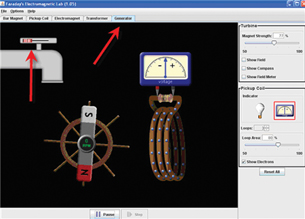
© PhET Interactive Simulations, University of Colorado. Some rights reserved.
- Adjust the magnetic strength and observe the magnitude of the voltage meter swing. Answer Analysis question LAB 3a.
- Adjust the water flow and observe the magnitude of the voltage meter swing. Answer Analysis question LAB 3b.
- Adjust the number of loops and observe the magnitude of the voltage meter swing. Answer Analysis question LAB 3c.
- Adjust the loop area and observe the magnitude of the voltage meter swing. Answer Analysis question LAB 3d.
Analysis
 Module 4: Lesson 3 Assignment
Remember to submit the answers to LAB 1 to LAB 6 to your teacher as part of your Module 4: Lesson 3 Assignment.
LAB 1. “Pickup” coil: how does the direction of the movement of the magnet affect the direction of the deflection on the voltage meter?
LAB 2. “Light bulb”: how does the speed of the magnet or coil affect the light?
LAB 3. “Generator”: describe how each of the following factors influences the magnitude of the deflection:
- strength of the magnetic field
- speed of the magnet passing the coil (adjusted by changing the water flow)
- the number of loops
- the loop area
LAB 4. Explain why the generator effect would occur in the same way if the wire were moved rather than the magnet.
Conclusions
LAB 5. Summarize the factors that determine the magnitude and direction of the induced current when there is relative motion between a magnetic field and a conductor.
Looking Ahead
LAB 6. Describe the change in the direction (sign) of the voltage as the magnet spins. Note that this “flip” in direction does not happen with a battery (direct current, or DC, voltage source). This generator, therefore, is not generating direct current! It is an AC (alternating current) generator.
 Self-Check
SC 3. Based on your results from the lab you just completed, which of the three coils in “Figure 12.37” in the “Inquiry Lab” would produce the most current?
Self-Check Answers
Contact your teacher if your answer varies significantly from the answer provided here.
SC 3. The larger loop would produce the most current.
 Module 4: Lesson 3 Lab—The Curious Relationship Between Motors and Generators
Lenz’s law: the direction of a magnetically induced current is oriented such that it produces a magnetic field, which opposes the motion causing it
Refer to the “Inquiry Lab” on page 616 of your textbook. Then watch the simulation 12–7 Inquiry Lab. According to the observations in the simulation, when a magnet falls through a metal pipe conductor, it generates an induced current in the conductor. The direction of this induced current produces its own magnetic field that “opposes” the motion of the falling magnet causing it. This slows down the magnet extending the time it takes to fall through the pipe. This process is known as Lenz’s law.
Example Problem 3. A bar magnet moves towards and then away from a solenoid connected to a galvanometer. In which direction is the induced current when the magnet approaches, and when it moves away from the solenoid?
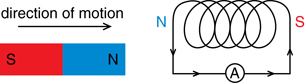
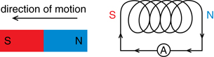
In the diagram, if the bar magnet moves towards the solenoid, the induced current (left to right through the ammeter) will be in a direction that produces a similar pole (north on the left of the solenoid), repelling the approaching magnet. If the bar magnet moves away, the induced current reverses direction (right to left through the ammeter), reversing the poles of the solenoid (south on the left of the solenoid) to attract the leaving magnet. You can observe this in the video clip on Faraday’s research into electromagnetic induction in the Watch and Listen activity below.
 Watch and Listen
The video Electromagnetic Induction will explain Faraday’s work on electromagnetic induction. If you have not completed Math 31, ignore the equations at the end of the video as they involve calculus and are beyond the scope of Physics 30.
Therefore, you can assign the magnetic poles of the solenoid based on Lenz’s law. Using the left-hand rule for solenoids, grasp the coil with your thumb pointing in the direction of the magnetic field within the coil (which is from the south pole to the north pole). Your fingers then wrap around the coil in the direction of electron flow.
Lenz’s law is a direct consequence of the conservation of energy. Consider the falling magnet in a conductor, which you saw in Inquiry Lab 12–7. If the induced current in the conductor, caused by the motion of the falling magnet, were orientated in such a way that it produced a magnetic field supporting the movement of the magnet, it would cause it to accelerate downward at a greater rate. That would increase the current in the conductor, which would lead to a further increase in the downward acceleration of the magnet, leading to an even greater induced current and magnetic field, producing greater accelerations, and so forth. This would mean that a magnet dropped into a metal pipe would accelerate like a bullet and shoot out of the lower end! A positive feedback loop such as this would be creating energy, violating the universal law of the conservation of energy.
 Read
Read
Read “Lenz’s Law” on pages 617–619 of the textbook.
Module 4: Lesson 3 Assignment
Remember to submit the answer to A 4 to your teacher as part of your Module 4: Lesson 3 Assignment.
A 4. Fill in the "?" with the missing information in each of the following diagrams. In the diagrams a magnet is either dropped down or pulled up through a cylinder encircled by a coil conductor. Remember that current is e- flow.
a. 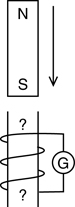 b.
b. 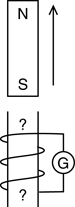 c.
c. 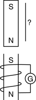 d.
d. 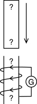 e.
e. 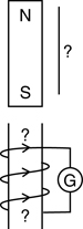 f.
f. 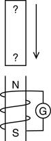
© Paul Laragy/shutterstock
 Discuss
D 1. Would two parallel wires carrying a current in opposite directions repel or attract one another? Include a diagram in your response. Refer to page 607 of your textbook to get started.
D 2. Post your response to the discussion area of your class. Read the postings of at least two other students.
Module 4: Lesson 3 Assignment
Remember to submit the answer to D 3 to your teacher as part of your Module 4: Lesson 3 Assignment.
D 3. Based on the other students’ responses, revise your answer to D 1 and comment on the other students’ answers.
Discussion Scoring Guide
| Principles involved: magnetic field around current-carrying conductors, magnetic forces | ||||
Criteria |
Level 1 |
Level 2 |
Level 3 |
Level 4 |
Knowledge |
||||
Demonstrates understanding of the situation, physics principles and technology, and their connections. |
Demonstrates a vague and sometimes incorrect understanding of the physics principles involved. Obvious irrelevant or missing information. |
Demonstrates a basic understanding of the physics principles involved. May exhibit minor mistakes or vague information or application to the situation. |
Demonstrates a good understanding of the physics principles involved and applies them properly to the given situation. All necessary information is given. |
Demonstrates a superior understanding of the physics principles involved and their application to the situation. All applications are considered in detail. |
Reflection |
||||
The post shows reflection on one’s own and other students’ work. Contributes to the group discussion. |
Does not make an effort to participate. Seems indifferent to discussion. |
Occasionally makes meaningful reflections on the group’s efforts or discussions. Marginal effort is shown to become involved with the group or discussion. |
Frequently makes meaningful reflections on the group’s efforts and presents relevant viewpoints for consideration by the group. Interacts freely with group members. |
Regularly attempts to motivate the group discussion and delve deeper into concepts. Interacts freely and encourages all group members. |
Content and presentation of discussion summary |
||||
The information is logically arranged in a clear and concise manner. |
The information is poorly organized with many concepts implied. Irrelevant or rambling sentences make reading difficult. |
The information is somewhat organized with implied concepts. Excessive words or awkward sentences are used, which hinder reading. |
The information is well-organized and logically arranged. All concepts are explicitly explained. There are a few awkward but understandable sentences. |
The information is well-organized and very easy to understand. Well-worded sentences make reading pleasurable. |