Module 5
1. Module 5
1.13. Page 2
Module 5—Wave Theory of Light
Explore
© Image courtesy of shutterstock.com
The Law of Reflection
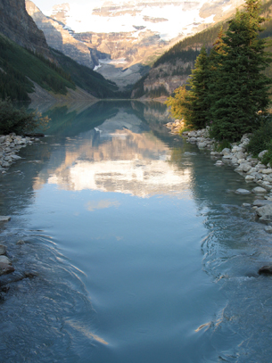
In the photo on the right, light is reflected from a mountain stream. Notice that the image seen in the centre, where the water forms a smooth, flat surface, is very clear. Also observe that the image is lost near the edges of the stream where the water is disturbed by the shoreline. Can this help explain how and why an image forms as light reflects from a surface?
Light travels in straight lines, as you learned in Lesson 1. The oscillating, perpendicular electric and magnetic fields propagate at right angles to both fields in a straight line. This is called rectilinear propagation. When the EMR wave encounters a smooth, flat surface, such as the water in the centre of the stream, it exhibits regular, specular reflection.
Specular reflection can be illustrated using a ray diagram, which identifies the path of the light using arrows.
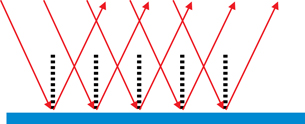
Notice that the organization of the light rays is maintained, but the orientation is reversed.
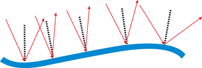
A ray diagram can also explain why an image does not form near the sides of the stream where the surface is rough. This type of reflection is called diffuse or irregular reflection.
Predicting the path of the reflected light, for both regular and irregular reflection, is based on the law of reflection. The simulation Light Reflection will be used to explore the law of reflection.
- Open the Light Reflection simulation, and
select one mirror (
 ) mode.
 - Click the “Show Calcs” button (
 ). A box with the Θin and Θout values will appear.
You should see an image similar to the one shown here. Take note of the labels and definitions that do not appear on the simulation display.
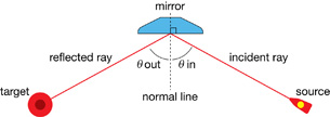
incident ray: an incoming ray of light
reflected ray: an outgoing ray of light
Θin: the angle between the incident ray and the normal line
Θout: the angle between the reflected ray and the normal line
 Module 5: Lesson 3 Assignment
Remember to submit your answers to LAB 1 and LAB 2 to your teacher as part of your Module 5: Lesson 3 Assignment.
LAB 1. The mirror angle can be adjusted using the angle slider (![]() ). Adjust the mirror position by clicking and dragging the mirror on the screen.
). Adjust the mirror position by clicking and dragging the mirror on the screen.
Adjust the position and/or angle of the mirror. Record the values for Θin and Θout for five different rays when the mirror is at various angles or positions. Record your observations.
Θin |
Θout |
|
|
|
|
|
|
|
|
|
|
LAB 2. The law of reflection is one of the most basic of all laws in optics. It relates the angle of incidence to the angle of reflection. On the basis of the investigation that you just performed, state the law of reflection.
 Try This
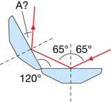
TR 1. Two mirrors are joined at a 120°-angle (as shown in the diagram). An incident ray contacts the first mirror at an angle of 65° to the normal. Calculate the angle, A, that the ray has with respect to the normal line of the second mirror. Hint: Remember that the sum of the interior angles in a triangle is 180°.
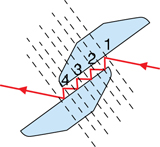
TR 2. Orient both mirrors so that multiple reflections occur and the final reflected ray is still travelling in its original direction. How must the mirrors be oriented for this to happen?
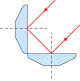
TR 3. Orient the mirrors so that they meet at a right angle (as shown in the ray diagram given). Mirrors in this configuration form what is called a corner reflector. Position the mirrors so that a multiple reflection occurs (e.g., the ray hits both surfaces), but be sure to maintain the 90° orientation between the mirrors. What special property does the direction of the reflected ray have?
TR 4. Corner reflectors are commonly used in reflective tape on clothing and in roadside reflectors. Explain why this technology is particularly effective for nighttime visibility applications.