Module 5
1. Module 5
1.20. Page 3
Module 5—Wave Theory of Light
 LAB: Determining the Refractive Index of a Variety of Materials
Retrieve your copy of the Module 5: Lesson 4 Assignment.
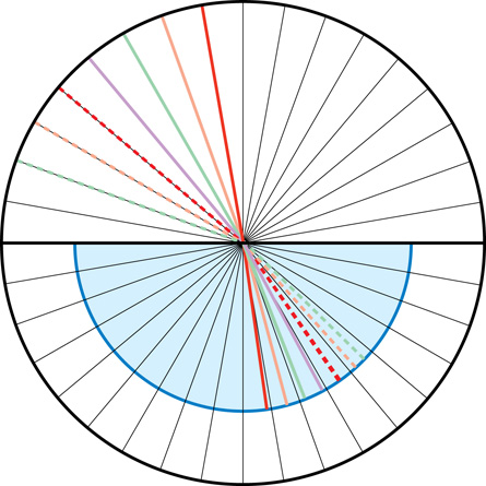
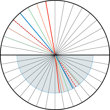
Read “Inquiry Lab” on page 671 of your textbook before performing this lab. See the two images that follow to collect your observations. The same wavelength of light was used. The lines are coloured to let you match the incident ray with the refracted ray. The semi-circular dish (light blue) is placed on a circular polar paper that acts like a 360° protractor. The polar paper has a radial line every ten degrees. You will have to use a real protractor to measure or you will estimate the values between the lines.
Note: Don’t forget to measure your angles from the normal to the surface.
Water Refractions
Ethanol Refractions
Problem
What are the refractive indexes of water and ethanol?
Materials
- polar coordinate paper
- graphing paper
- water
- ethanol
- single-slit ray box or laser
- semicircular plastic dish
Procedure
Follow the Procedure on page 671 of your textbook. If you do not have access to a supervised laboratory, use the diagrams to fill in the table and to answer the questions that follow.
Observations
 Module 5: Lesson 4 Assignment
Remember to submit your answers to LAB 3, LAB 4, and LAB 5 to your teacher as part of your Module 5: Lesson 4 Assignment.
LAB 3. Use the Water Refractions diagram and the Ethanol Refractions diagram to gather data regarding water refractions and ethanol refractions. Record your data for water refractions and your data for ethanol refractions in a table like the following. (Note: You will need two tables.)
θ1 |
θ2 |
sin θ1 |
sin θ2 |
|
10 |
|
|
|
|
20 |
|
|
|
|
30 |
|
|
|
|
40 |
|
|
|
|
50 |
|
|
|
|
60 |
|
|
|
|
70 |
|
|
|
|
Graph
LAB 4. Plot a graph of the sine of the angle of incidence versus sine of the angle of refraction. Plot a line for water and a line for ethanol. Calculate the slope of each line on this graph.
Calculations and Questions
LAB 5. Complete “Analysis” questions 3–8 on page 671 of your textbook.
Total Internal Reflection
According to the second rule of thumb for refraction, when light travels from a high-index, optically dense slow medium into a low-index, optically les dense faster medium, the ray bends away from the normal. If the angle of refraction reaches or exceeds 90°, the beam is unable to escape the high-index medium. This phenomenon is called total internal reflection and it can be demonstrated using the Light Refraction simulation.
Module 5: Lesson 4 Assignment
Remember to submit your answers to LAB 6 to your teacher as part of your Module 5: Lesson 4 Assignment.
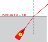
LAB 6. Using the Light Refraction simulation, set the refractive index of the top layer to equal 1.00 and the refractive index of the bottom layer to equal 1.33. Position the laser pointer in the bottom layer near the left side and project it upward (as shown on the right).
- Complete Table 3 by rotating the laser pointer to the angles specified and calculating the angle of refraction using Snell’s Law. (It has been manipulated to solve for the angle of refraction.) Note: Refraction will not occur for all the angles in the table.
Table 3: Total Internal Reflection Data
| θ1 |
|
θ2 |
35° |
|
|
40° |
|
|
45° |
|
|
50° |
|
|
55° |
|
|
- What is the maximum possible angle of incidence that still causes refraction? Describe what happens to the ray of light if the angle of incidence exceeds this value.
The maximum possible angle of incidence that will still cause refraction is known as the critical angle. The critical angle can be calculated by assuming the angle of refraction is 90°. At this point, the ray is refracted parallel to the interface between the mediums. Any increase in the incident angle will cause the refracted ray to no longer refract but to bounce, or reflect, back into the higher index medium.