Module 5
1. Module 5
1.25. Page 2
Module 5—Wave Theory of Light
 Explore
converging lens: a lens that refracts rays travelling parallel to the principal axis inward to the focal point of the lens
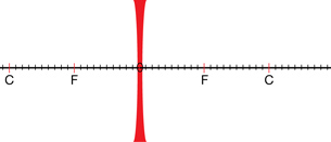
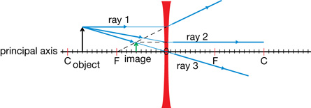
diverging lens: a lens that refracts rays travelling parallel to the principal axis outward so that they appear to have originated or passed through the virtual focal point of the lens
A thin lens, similar to that found in the human eye, is a circular piece of transparent material with a spherically shaped surface. With any curved lens, light rays will be refracted at various angles depending on where they contact the curved surface. There are two types of thin lenses.
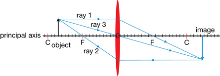
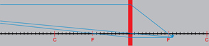
A converging lens with convex surfaces refracts rays that are parallel to the principal axis toward a focal point producing a real image (as shown in the diagram).
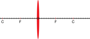
A diverging lens with concave surfaces refracts rays that are parallel to the principal axis outward so that they appear to have originated from a virtual focal point. Therefore, a diverging lens can only produce a virtual image.
The following table summarizes all the relevant labels for each ray diagram.
Label |
Definition |
C |
centre of curvature, the radius of the spherical surface of the lens |
F |
focal point, primary on the object side, secondary on the other side |
O |
optical centre of the lens |
principal axis |
imaginary line that is perpendicular to the lens surface at the optical centre |
ray 1 |
travels parallel to the principal axis and is refracted through, or appears to have passed through, the principal focus |
ray 2 |
travels through, or appears to have passed through, the secondary focus and emerges parallel to the principal axis |
ray 3 |
passes straight through the optical centre (See “Physics Insight” on page 678 of your physics textbook.) |
As with ray diagrams used for curved mirrors, many rays produce the image but only a few are required to identify the image characteristics. The three rays used in the illustrations can be used with any ray diagram to predict the image characteristics.
Recall the following image characteristics from Lesson 3.
Image Characteristic |
Definition |
magnification |
ratio of the size of the image to the size of the object |
attitude |
vertical orientation of the image relative to the object |
position |
where the image and object are located relative to the reflecting surface |
real or virtual image |
a real image forms where light rays converge, a virtual image forms where light rays “appear” to have converged or originated |
A simulation will be used to explore the image characteristics for both converging and diverging lenses.
 Module 5: Lesson 5 Assignment
Remember to submit your answers to LAB 1 and LAB 2 to your teacher as part of your Module 5: Lesson 5 Assignment.
LAB 1. Open the Thin Lens simulation and select “Lens” from the drop-down menu (if needed).
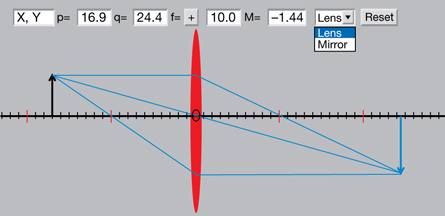
© F. Hwang, NTNU JAVA Virtual Physics Laboratory. Used with permission.
Click the object arrow and move it to various locations on the principal axis. Using the simulation as a guide, draw ray diagrams and describe the image characteristics when the object is located at the positions listed in Table 1. The first one is done as an example. You can find a copy of the table in your Module 5: Lesson 5 assignment document.
Table 1: Using Ray Diagrams to Predict Image Characteristics—Converging Lens
Object Position |
Ray Diagram |
Image Characteristics |
very far away |
|
The image is real, inverted, much smaller than the object, and is located at F. |
outside C |
|
|
at C |
|
|
between C and F |
|
|
at F |
|
|
inside F |
|
|
LAB 2. Switch the lens in the simulation to a diverging lens by making the focal length negative (![]() ). Complete Table 2.
). Complete Table 2.
Table 2: Using Ray Diagrams to Predict Image Characteristics—Diverging Lens
| Object Position | Ray Diagram |
Image Characteristics |
very far away |
|
The image is real, inverted, much smaller than the object, and is located at F. |
outside C |
|
|
at C |
|
|
between C and F |
|
|
at F |
|
|
inside F |
|
|